Apparatus and methods for gas production during pressure letdown in pipelines

a technology of pipelines and apparatus, applied in the direction of gas pressure propulsion mounting, gas/liquid distribution and storage, plural diverse prime-mover propulsion mounting, etc., can solve the problems of large emissions of dilute co2/sub>2 into the atmosphere, inconvenient storage of gas, and high cost of heating gas. achieve the effect of producing and efficiently storing other gases

Inactive Publication Date: 2007-07-19
MCDONALD DUNCAN +1
View PDF10 Cites 29 Cited by
  • Summary
  • Abstract
  • Description
  • Claims
  • Application Information

AI Technical Summary

Benefits of technology

[0134] The apparatus can be used to produce and efficiently store other gases. For example, the oxygen that is produced in electrolysis of water can also be cooled, compre

Problems solved by technology

Industry practice has been to use isenthalpic valves to reduce pressure from mainline natural gas transmission conditions to local distribution facilities at meter (or letdown) stations strategically located near city gates; such valves recover no potential energy and incur a cost for heating the gas to avoid high pressure blow-by of valve packing, hydrate formation and downstream frost bulges.
Hence, although pressure reduction from mainline transmission conditions to local distribution networks through valves is a reliable and simple technique, it is an energy inefficient process.
While the process is reasonably energy efficient, it results in massive emissions of dilute CO2 to the atmosphere.
Unfortunately, the expense of electricity has hampered the adoption of this

Method used


Image

  • Apparatus and methods for gas production during pressure letdown in pipelines
  • Apparatus and methods for gas production during pressure letdown in pipelines
  • Apparatus and methods for gas production during pressure letdown in pipelines

Examples


example 2

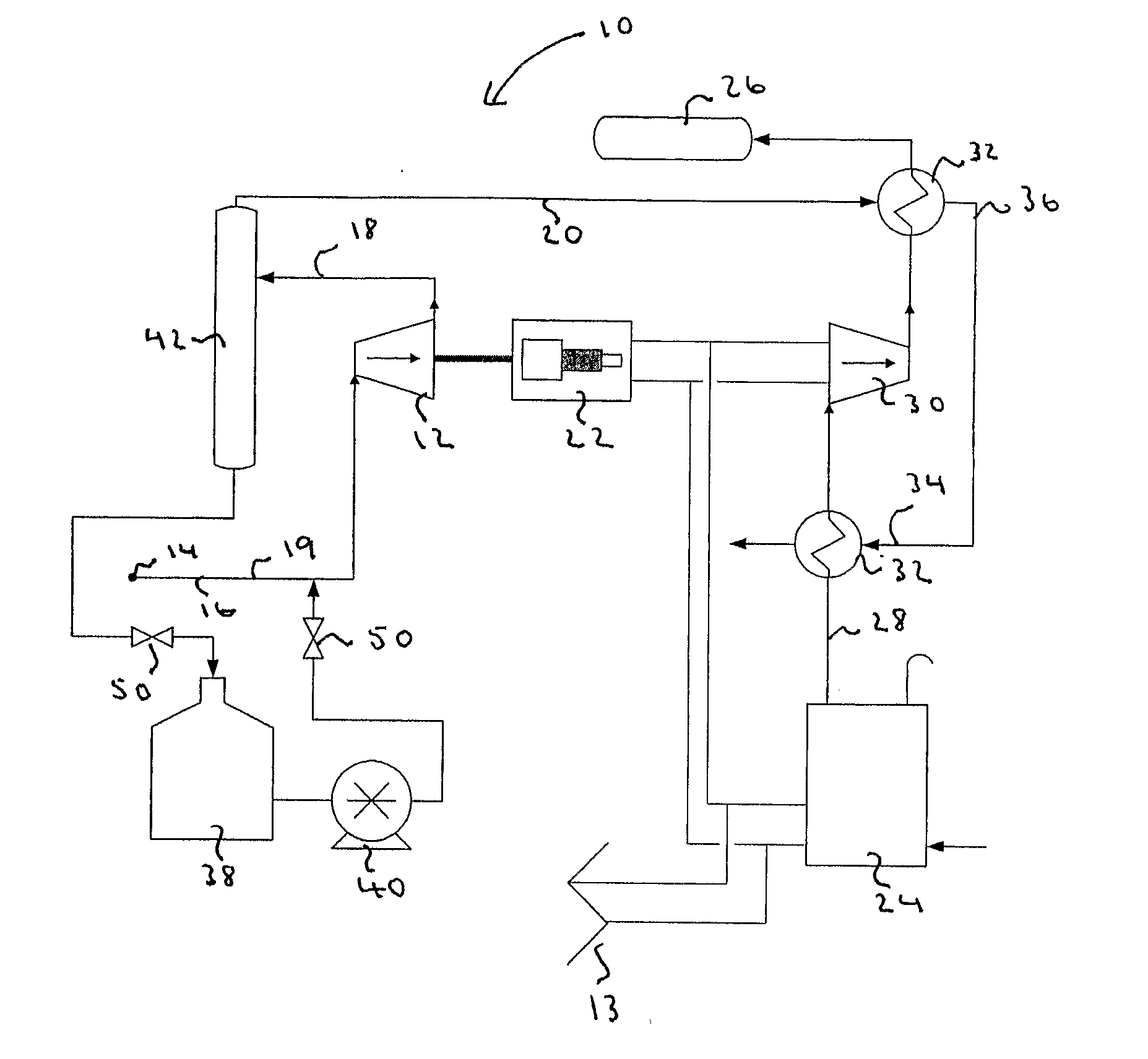
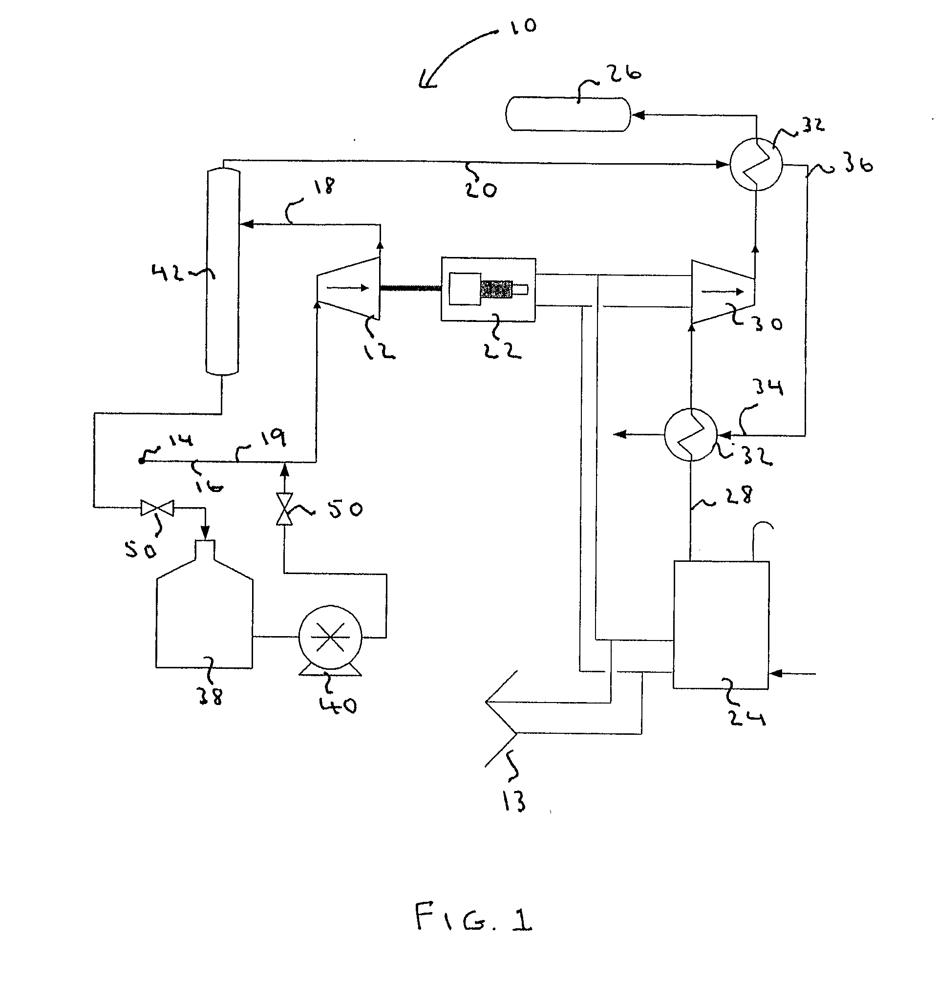
[0129] In a second example compression energy is recovered through a turbo-expander coupled to an electrical generator for electricity production. Turbo-expanders are common pieces of equipment in the natural gas production and chemical industries where they are used for dew point control and liquids extraction.

example 3

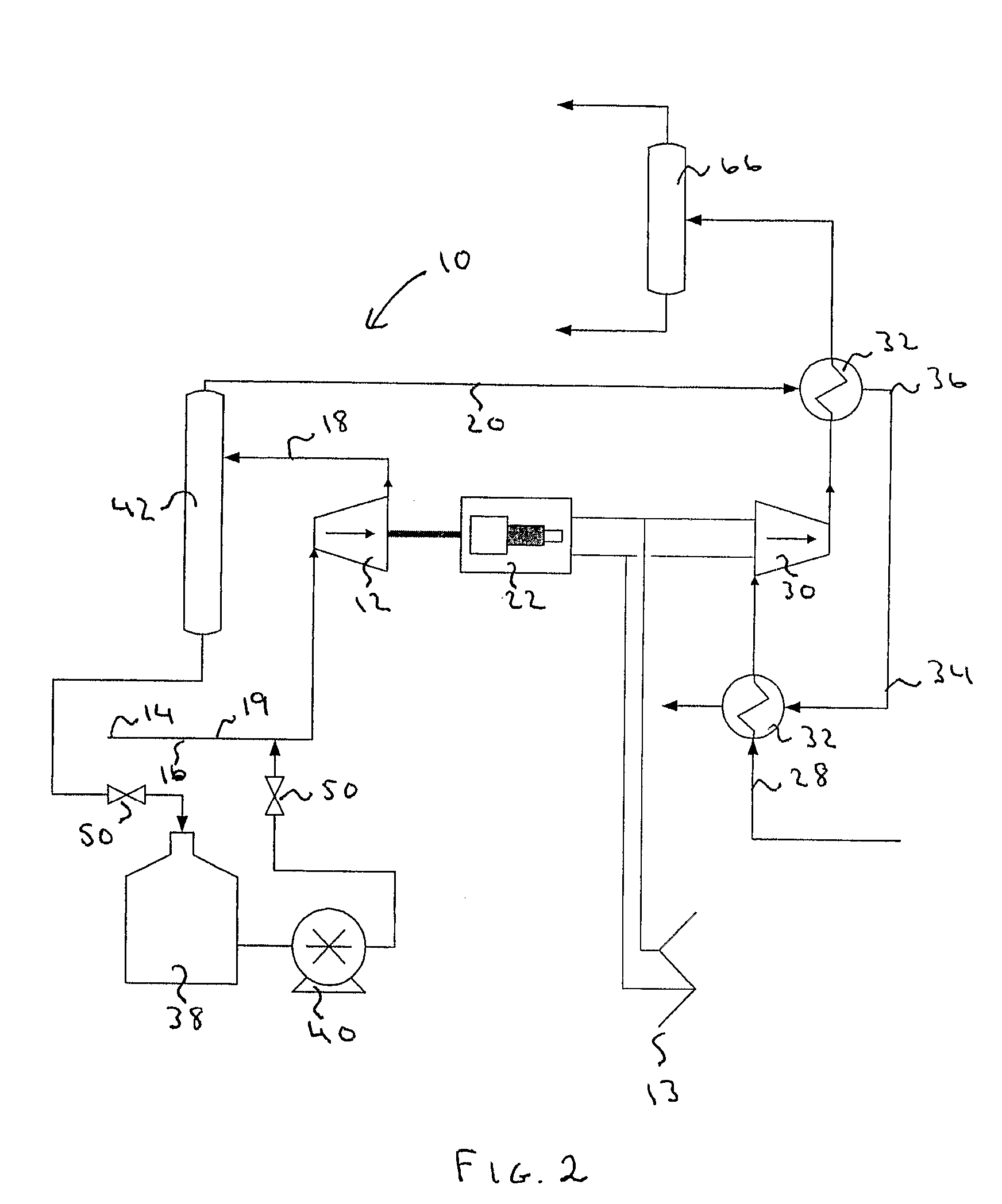
[0130] In a third example the cooling stream at hydrogen production plants is used to capture CO2 which can then be made available for enhanced oil recovery and sequestration opportunities. Large SMR (steam methane reforming) hydrogen plants use natural gas as the process stream and include an intermediate stream containing H2, CO, CO2 and CH4. The present invention provides a turbo-expander to produce a cooling stream which is heat exchanged with the intermediate stream to extract CO2 for EOR (Enhanced Oil Recovery) or sequestration.

[0131] The electrical output of the electrical generator is used to drive a gas compressor which raises the pressure of the intermediate stream thereby enabling continuous CO2 condensation and removal as a liquid. After CO2 removal, the enriched portion of the intermediate stream is returned to the hydrogen plant.

example 4

[0132] In a fourth example the cooling stream is used to improve the energy efficiency and economics of front-end air separation in advanced recycle combustion systems (e.g. at CCGT power plants). Advanced recycle combustion plants include a front-end air separation plant that concentrates the oxygen content by cryogenic means. The present invention provides a turbo-expander to produce a cooling stream which is heat exchanged with the incoming air to increase the efficiency in front-end air separation. The concentrated oxygen is diluted with recycled flue gas high in CO2 resulting in an oxidizing stream that when used for combustion will not produce NOx. The cold sink can also be used to reduce CO2 capture costs as above.


PUM


Abstract

Apparatus, methods and an installation are provided for reducing pressure in a carrier line, such as a natural gas pipeline, and capturing the resultant waste energy. The apparatus is comprised of a flow converter for gaseous communication with a carrier line and an electricity generator mechanically linked to the flow converter for transforming the excess energy resulting from the pressure drop into electrical energy, such that in use, the energy released from the pressure drop can be captured and utilized for the production of gases such as hydrogen.

Description

FIELD OF THE INVENTION [0001] The present invention relates to apparatus located at pipeline pressure reduction sites for capturing energy and utilizing the cooling stream. Further, the invention provides for methods of use of the captured energy and the cooling stream. More specifically, the invention relates to using the pressure reduction in natural gas pipelines for the production and efficient storage of processed gases. BACKGROUND OF THE INVENTION [0002] Thousands of kilometres of high-pressure natural gas transmission pipelines have been installed in North America and Europe to link producing fields with major energy consumption locations in almost every city and town. In North America many of these systems are interconnected with storage facilities providing a mature, highly integrated clean energy delivery network with >5.4 million hp of gas turbine drivers installed as of 1994 and >232 gas storage facilities as of 1997 (aggregate capacity of >3.3 Tcf). High-pressu...

Claims


Application Information

Patent Timeline
IPC IPC(8): B60K6/04B60K6/20
CPCY02E60/34F17D1/04
Inventor MCDONALD, DUNCANBAILEY, RICHARD A.
Owner MCDONALD DUNCAN
Why Eureka
Try Eureka