
Briquette for use as steelmaking material and method of manufacturing the same

a technology of briquettes and steelmaking materials, applied in the direction of process efficiency improvement, etc., can solve the problems of reducing the use of reducing agents in the steelmaking process, and achieve the effect of reducing and increasing the use of reducing agents

Inactive Publication Date: 2007-07-19
JTEKT CORP
View PDF5 Cites 1 Cited by
  • Summary
  • Abstract
  • Description
  • Claims
  • Application Information

AI Technical Summary

Benefits of technology

[0006] The briquette for use as steelmaking material, having the above composition, is formed by solidifying the shot waste with the solidification assistant. Therefore, the briquette is capable of exhibiting an adequate degree of mechanical strength so as to be easy to handle during transportation, storage and the like. Because of the dry solid mass nature, the briquette directly charged into a blast furnace involves no fear of causing bumping or being scatteringly carried upward to be discharged from the furnace. What is more, the briquette contains the great number of shot beads formed from pure iron having an iron content of 90 wt % or more. This leads to a decreased use of a reducing agent in a steel making process. Thus, the briquette permits the shot waste to be reused as a high-quality steelmaking material, contributing to the environmental conservation as well as to the reduction of the disposal cost of the shot waste.
[0020] In the briquette manufacture methods of the first and second aspects, the solidification assistant may preferably be at least one selected from the group consisting of sodium silicate, coloidal silica, aluminum phosphate and asphalt emulsion. Thus, the shot waste can be more easily and rigidly solidified. According to the briquette manufacture method of the second aspect, in particular, the brittle compact containing the oil can be solidified easily and rigidly.

Problems solved by technology

This leads to a decreased use of a reducing agent in a steel making process.

Method used


Image

  • Briquette for use as steelmaking material and method of manufacturing the same
  • Briquette for use as steelmaking material and method of manufacturing the same
  • Briquette for use as steelmaking material and method of manufacturing the same

Examples


first embodiment

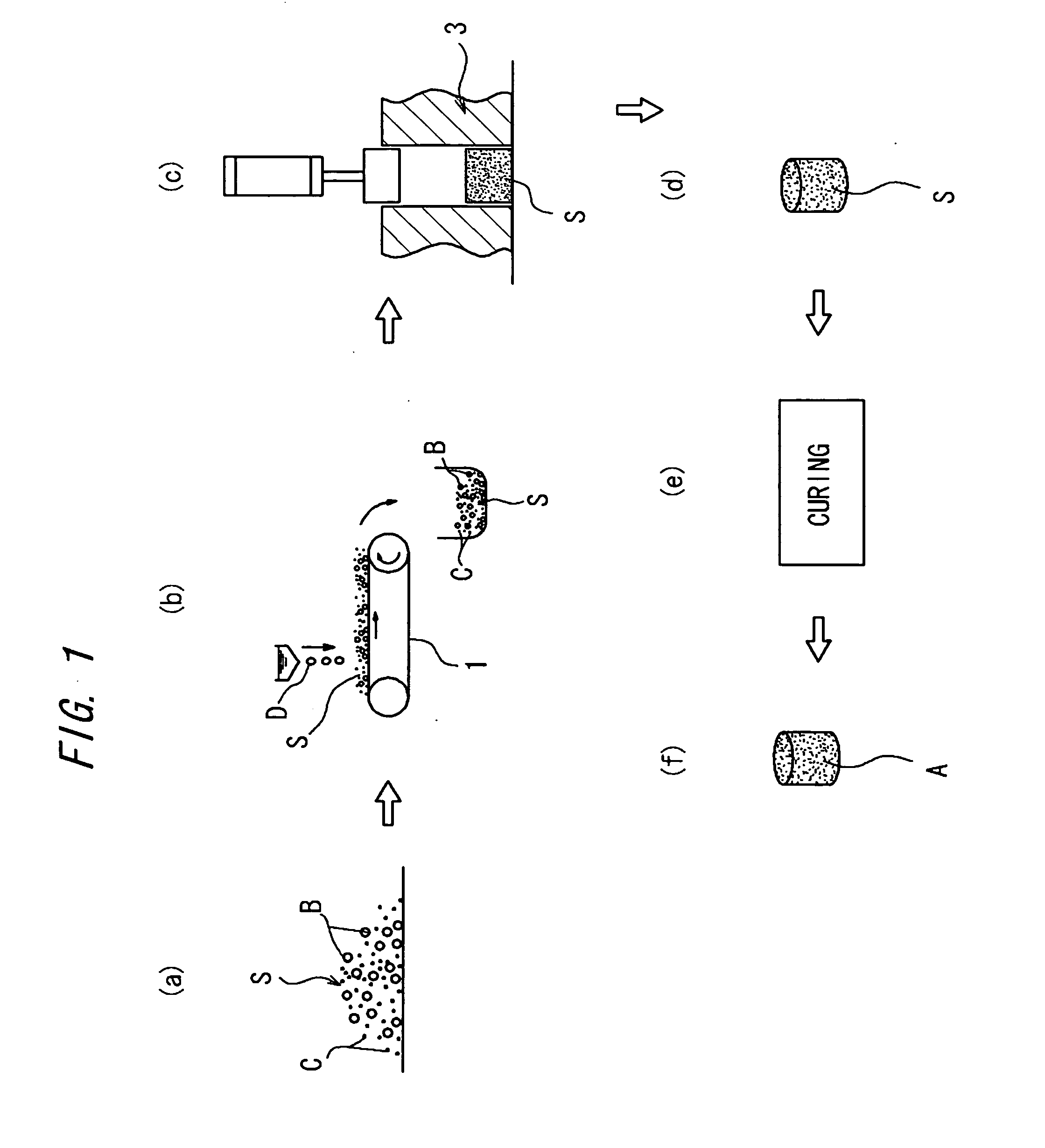
[0026]FIG. 1 is a step chart illustrating a method of manufacturing a briquette for use as steelmaking material according to the invention. In the manufacture of a briquette A, shot waste S (FIG. 1(a)) resulting from shot blasting a ferrous metal is first transported by means of a belt conveyor 1, while a solidification assistant D in liquid form is added dropwise to the shot waste S (FIG. 1(b)).

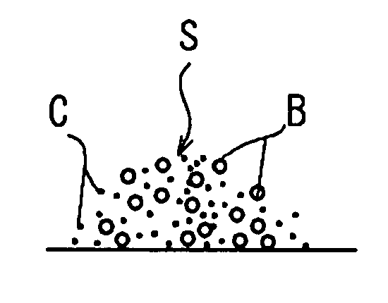
[0027] The shot waste S includes a great number of spent shot beads B thinned down to less than a predetermined particle size by the shot blasting process, a ferrous powder metal C and the like. The powder metal contains oxidized powder iron in an amount of 60 to 65 wt %. A 100% sodium silicate solution is used as the solidification assistant D.

[0028] Next, the shot waste S admixed with the solidification assistant D is compression molded by means of a press using a mold 3 (FIG. 1(c), FIG. 1(d)). The compression molding allows the solidification assistant D added to the shot waste S to perm...

second embodiment

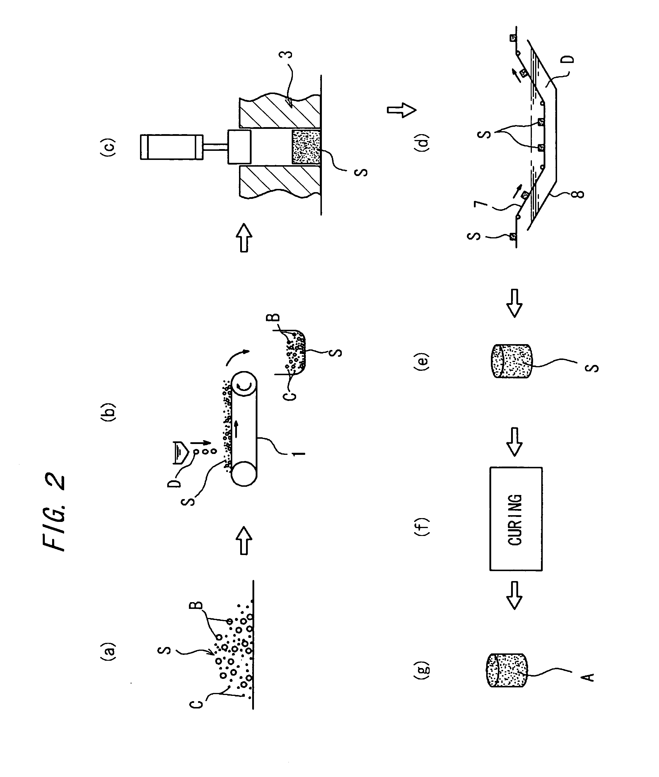
[0032]FIG. 2 is a step chart illustrating a method of manufacturing a briquette for use as steelmaking material according to the invention. This embodiment differs from the embodiment shown in FIG. 1 in that the manufacture process further includes a step of impregnating the solidification assistant D into the shot waste S, the step being interposed between the step of compression molding the shot waste S and the step of drying the compression molded shot waste S.

[0033] The impregnation of the solidification assistant D is performed as follows, for example. As carried on a belt conveyor 7, the compression molded shot waste S is dipped in the solidification assistant D filled in a tank 8 (FIG. 2(d)). Sodium silicate diluted with water is used as the solidification assistant D filled in the tank 8. Thus is ensured a good permeability of the solidification assistant D into the compression molded shot waste S. According to this embodiment, the mechanical strength of the briquette A is f...

third embodiment

[0037]FIG. 4 is a step chart illustrating a method of manufacturing a briquette for use as steelmaking material according to the invention. In the manufacture of the briquette A, cotton-like agglomerations M are first prepared by sprinkling the shot waste S on cutting sludge E (FIG. 4(a)) being transported on the belt conveyor 1, the cutting sludge resulting from cutting a ferrous metal. The cotton-like agglomerations are admixed with the shot waste S (FIG. 4(b)). The cutting sludge E is a cotton-like material containing the cutting residue particles and the cutting fluid. The shot waste S results from shot blasting a ferrous metal, containing spent shot beads thinned down to less than a predetermined particle size by the shot blasting process and a powder material containing oxidized powder iron in an amount of 60 to 65 wt %. A mixing ratio of the shot waste S is 10 to 30 wt %. If the cotton-like agglomerations M contains the shot waste S in an amount of less than 10 wt %, the briq...


PUM

PropertyMeasurementUnit
wt %aaaaaaaaaa
wt %aaaaaaaaaa
shapeaaaaaaaaaa

Abstract

A briquette for use as steelmaking material and a method of manufacturing the same, capable of effective reusing of the shot waste. After dropping a solidification assistant into shot waste consisting of powder metal containing iron powder and shot beads, the shot waste is compression molded. The compression molded shot waste is dried. Alternatively, the shot waste is admixed with cutting sludge containing ferrous-metal cutting residue particles and a cutting fluid containing oil and water, thereby forming cotton-like agglomerations. The cotton-like agglomerations are compression molded, thereby forming a brittle compact, which has the fibrous cutting sludge roughly sheared and which is removed of excessive water and oil. The brittle compact is impregnated with the solidification assistant, solidified and dried.

Description

TECHNICAL FIELD [0001] The present invention relates to a briquette for use as steelmaking material and a method of manufacturing the same. Particularly, the invention relates to a technique for effectively utilizing shot waste resulting from shot blasting a ferrous metal. BACKGROUND ART [0002] The shot waste resulting from shot blasting the ferrous metal generally contains a ferrous powder metal and spent shot beads (steel beads) in a total amount on the order of 75 to 95 wt %. Therefore, the aforesaid shot waste can offer an effective resource as a steelmaking material. Unfortunately, however, the shot waste is apt to ignite or to be scattered. Furthermore, the shot waste contains such a great number of shot beads that the shot waste is hard to be solidified by compression molding and the like. This leads to a disadvantage in the handling operations thereof such as transportation and storage. Accordingly, the reuse of the shot waste involves technical and cost disadvantages. In re...

Claims


Application Information

Patent Timeline
Patent Type & Authority Applications(United States)
IPC IPC(8): C22B1/24C22B1/243C22B1/248C22B7/00
CPCC22B1/24C22B7/00C22B1/248C22B1/243Y02P10/20
Inventor MATSUDA, MITSUMA
Owner JTEKT CORP
Learn More