Method for cleaning treatment chamber iIn substrate treating apparatus and method for detecting endpoint of cleaning

a technology for treating apparatus and cleaning process chamber, which is applied in the direction of cleaning hollow objects, instruments, coatings, etc., can solve the problems of hindering the oxidation process, reducing the oxidation rate, and contaminated process chambers used for the process, so as to achieve a significant shortening of the cleaning time

Inactive Publication Date: 2007-07-19
TOKYO ELECTRON LTD
View PDF7 Cites 51 Cited by
  • Summary
  • Abstract
  • Description
  • Claims
  • Application Information

AI Technical Summary

Benefits of technology

[0011] An object of the present invention is to provide a method for cleaning a process chamber contaminated with metal, such as tungsten, in a substrate processing apparatus, which can efficiently clean the process chamber.
[0012] Another object of the present invention is to provide a method for cleaning and a method for detecting the cleaning end point, which can find the end point in a simple way, when cleaning a process chamber contaminated with metal, such as tungsten, in a substrate processing apparatus.
[0031] According to the present invention, after a process chamber is contaminated with metal by performing a plasma process or the like on a substrate having a metal-containing film, the chamber is treated in-situ by plasma of a gas containing O2, without setting the chamber opened to the atmosphere. With this arrangement, metal components, such as tungsten, are oxidized and thereby sublimated, so the metal components, such as tungsten, are very effectively removed. Consequently, the cleaning time is significantly shortened, as compared to the conventionally cleaning process that requires a time period for setting the process chamber opened to the atmosphere, a time period for performing wet cleaning, a time period for performing re-exhaust, a time period for re-conditioning the process chamber after the exhaust, and so forth.
[0032] Further, according to the present invention, when dry cleaning is performed by plasma inside a chamber contaminated with tungsten, the emission intensity of hydrogen radical (H*) is monitored, so that the tungsten contamination quantity becomes easy to find. With this arrangement, the end point of the dry cleaning by plasma can be reliably determined. Consequently, it is possible to solve problems of the conventional cleaning method utilizing time management, such as contamination and re-cleaning due to insufficient cleaning, and excessive cleaning.

Problems solved by technology

In a process of this kind, an Si wafer including tungsten is handled, and thus the process chamber used for the process is contaminated with tungsten.
If this process chamber is used for subsequent selective oxidation, tungsten affects the process such that tungsten may be taken into devices as contaminants, and tungsten may hinder the oxidation process and decrease the oxidation rate.
However, conventionally, it has not yet been successful in utilizing dry cleaning to efficiently clean a process chamber contaminated with metal, such as tungsten (W).
Further, the end point of dry cleaning is difficult to find, and thus time management is utilized to determine the end of cleaning.
However, since time management is arranged to terminate cleaning with reference to a preset time, a problem arises such that the cleaning is insufficient or the cleaning time period is too long.
If the cleaning is insufficient, troublesome re-cleaning has to be performed, because deposits remaining in a chamber cause contamination.
If the cleaning time period is too long, time and energy are wastefully consumed.

Method used


Image

  • Method for cleaning treatment chamber iIn substrate treating apparatus and method for detecting endpoint of cleaning
  • Method for cleaning treatment chamber iIn substrate treating apparatus and method for detecting endpoint of cleaning
  • Method for cleaning treatment chamber iIn substrate treating apparatus and method for detecting endpoint of cleaning

Examples


first embodiment

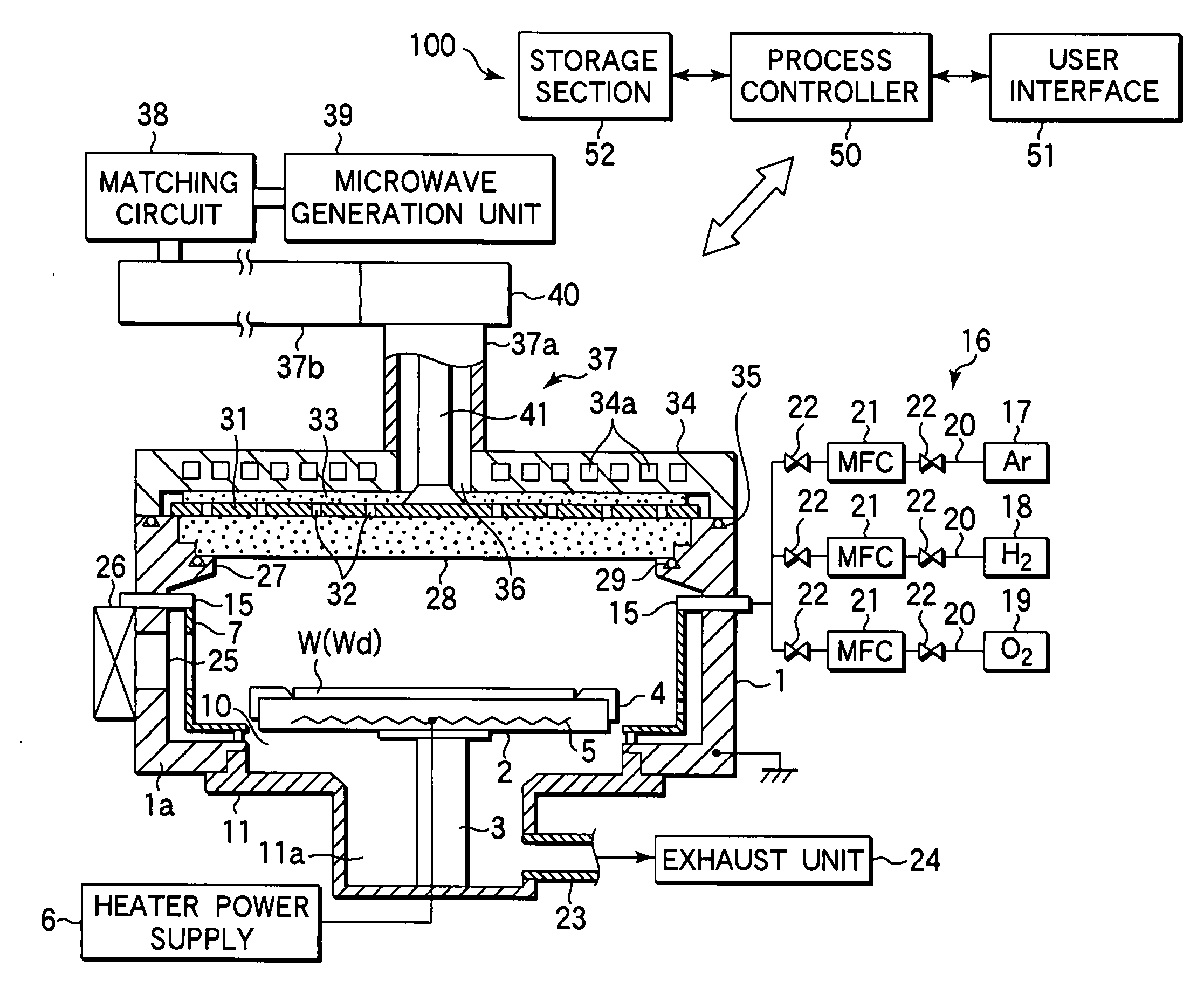
[0052]FIG. 1 is a sectional view schematically showing an example of a plasma processing apparatus to be subjected to a process chamber cleaning method according to the present invention.

[0053] This microwave plasma processing apparatus 100 is arranged as a microwave plasma processing apparatus of the RLSA (Radial Line Slot Antenna) type, in which an RLSA, i.e., a planar antenna having a plurality of slots formed with a predetermined pattern, is utilized to radiate microwaves guided from a microwave generation unit into a chamber to generate plasma. For example, this apparatus is used to perform a selective oxidation process on a poly-silicon sidewall of a gate electrode.

[0054] This plasma processing apparatus 100 includes an essentially cylindrical chamber 1, which is airtight and grounded. The bottom wall 1a of the chamber 1 has a circular opening 10 formed essentially at the center, and is provided with an exhaust chamber 11 communicating with the opening 10 and extending downwa...

second embodiment

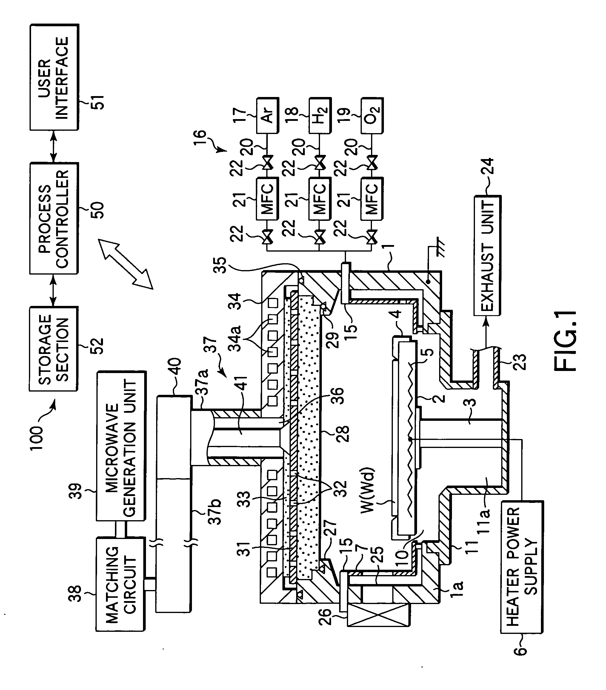
[0109] Next, an explanation will be given of a second embodiment according to the present invention.

[0110]FIG. 11 is a sectional view schematically showing an example of a plasma processing apparatus to be subjected to a process chamber cleaning method according to a second embodiment of the present invention.

[0111] This plasma processing apparatus 200 include an end point detecting function in addition to the plasma processing apparatus shown in FIG. 1. In FIG. 11, the same constituent elements as those in FIG. 1 are denoted by the same reference numerals, and the explanation thereof will be omitted.

[0112] This plasma processing apparatus 200 includes a translucent window 80 used for detecting the cleaning end point, in a lower portion of the sidewall of a chamber 1. A light receiver 81 is disposed adjacent to this window 80 and is electrically connected to a spectroscopy controller 82, such as a monochrometor, for measuring plasma emission intensity. The window 80 is located dis...


PUM

PropertyMeasurementUnit
temperatureaaaaaaaaaa
pressureaaaaaaaaaa
pressureaaaaaaaaaa

Abstract

In a substrate processing apparatus for performing a plasma process on a substrate including a tungsten-containing film, cleaning is performed for a process chamber. This cleaning includes, after the plasma process, supplying a gas containing O2 into the process chamber without setting the process chamber opened to the atmosphere, and generating plasma of the gas to clean the process chamber.

Description

TECHNICAL FIELD [0001] The present invention relates to a method for cleaning a process chamber and a method for detecting the cleaning end point, in a substrate processing apparatus. More specifically, the present invention relates to a method for cleaning a process chamber contaminated with metal and a method for detecting the cleaning end point. Further, the present invention relates to a computer program and a storage medium for executing the method. BACKGROUND ART [0002] In recent years, owing to the demands for higher integration degrees and higher operation rates of LSIs, design rules for semiconductor devices of LSIs are increasingly miniaturized. Along with this trend, the resistivity of transistor gate electrodes used in DRAMs or the like is required to be lower. Accordingly, tungsten (W)-containing films with a low resistivity have come into use for gate electrodes of this kind. For example, a tungsten polycide gate (a multi-layered film of WSi / poly-Si) and a tungsten pol...

Claims


Application Information

Patent Timeline
Patent Type & Authority Applications(United States)
IPC IPC(8): B08B6/00B08B9/00G06F19/00C23F1/00C23C16/00B08B7/00C23C16/44C23C16/52H01J37/32H01L21/3065H01L21/31
CPCB08B7/0035H01J37/32935H01J37/32862H01J37/32192H01L21/304H01L21/3065
Inventor OZAKI, SHIGENORINOGUCHI, HIDEYUKIKABE, YOSHIROISA, KAZUHIROSASAKI, MASARU
Owner TOKYO ELECTRON LTD
Why Eureka
Try Eureka