Gas supply system and processing system

a technology of gas supply system and processing system, which is applied in the field of processing system, can solve the problems of increasing pressure loss, difficulty in obtaining material gas of a desired flow amount, and decreasing the evaporation or sublimation of metallic compound material m correspondingly

Inactive Publication Date: 2007-07-19
TOKYO ELECTRON LTD
View PDF16 Cites 27 Cited by
  • Summary
  • Abstract
  • Description
  • Claims
  • Application Information

AI Technical Summary

Benefits of technology

[0073] Moreover, a gas outlet to which said gas passage is connected is provided in the ceiling portion of said material reservoir tank and a baffle plate member is provided to cover said gas outlet in order to prevent any metallic compound material other than gas from entering inside said gas outlet, as in another invention of the present application.
[0074] By providing the baffle plate member at the gas outlet in this way, the metallic compound material in the form of droplets or particles / powdery material except for gas can be prevented from flowing to the side of the processing apparatus without generating pressure loss.

Problems solved by technology

In the gas supply system described above on the other hand, the material, reservoir tank 2 and the processing apparatus 8 are wide apart and thus the length of the pipe of the gas passage 6 is elongated, resulting in quite an increase in pressure loss at this point.
Consequently, there has been difficulty in obtaining a material gas of a desired flow amount because the pressure inside the material reservoir tank 2 is increased corresponding to the pressure loss values, thus decreasing the evaporation or sublimation of the metallic compound material M correspondingly,
In this case, the metallic compound material M might possibly be placed inside the processing apparatus in a case that the metallic compound material M is solid, but this is not practical because the produced material gas flow cannot be controlled.
Moreover, especially in a case that the metallic compound material M is solid, there has been a problem that the flow amount of the produced material gas becomes unstable because an injection nozzle 12 for a carrier gas is provided inside the material reservoir tank 2 and is directed fixably at a specific point, thereby subliming and decreasing the particular part of the metallic compound material M having a direct contact with the gas injected from the injection nozzle 12 while the other part has less decrease, resulting in causing one-side wear.

Method used


Image

  • Gas supply system and processing system
  • Gas supply system and processing system
  • Gas supply system and processing system

Examples


Embodiment Construction

[0102] With reference to the attached figures, an embodiment of the gas supply system and processing system according to the present invention will be hereinafter explained in detail.

(First Invention)

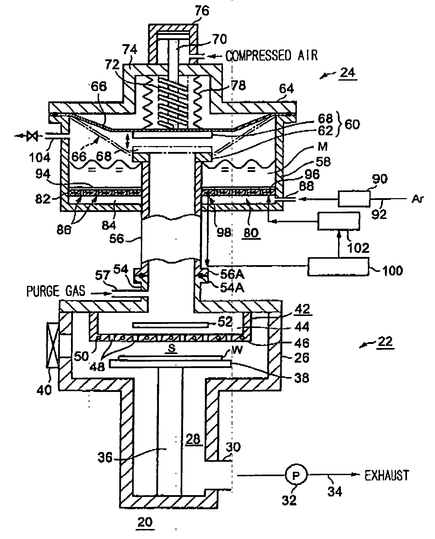
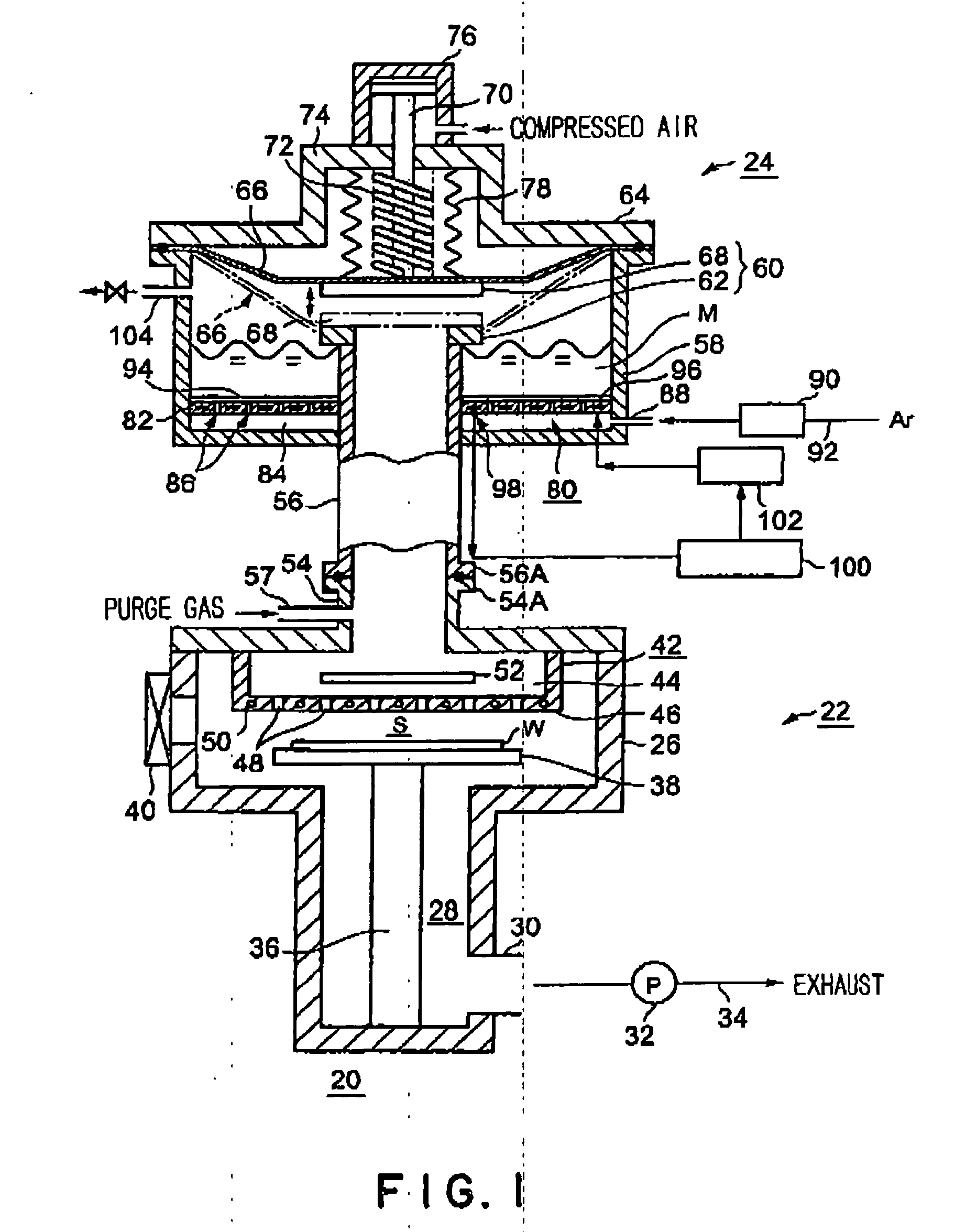
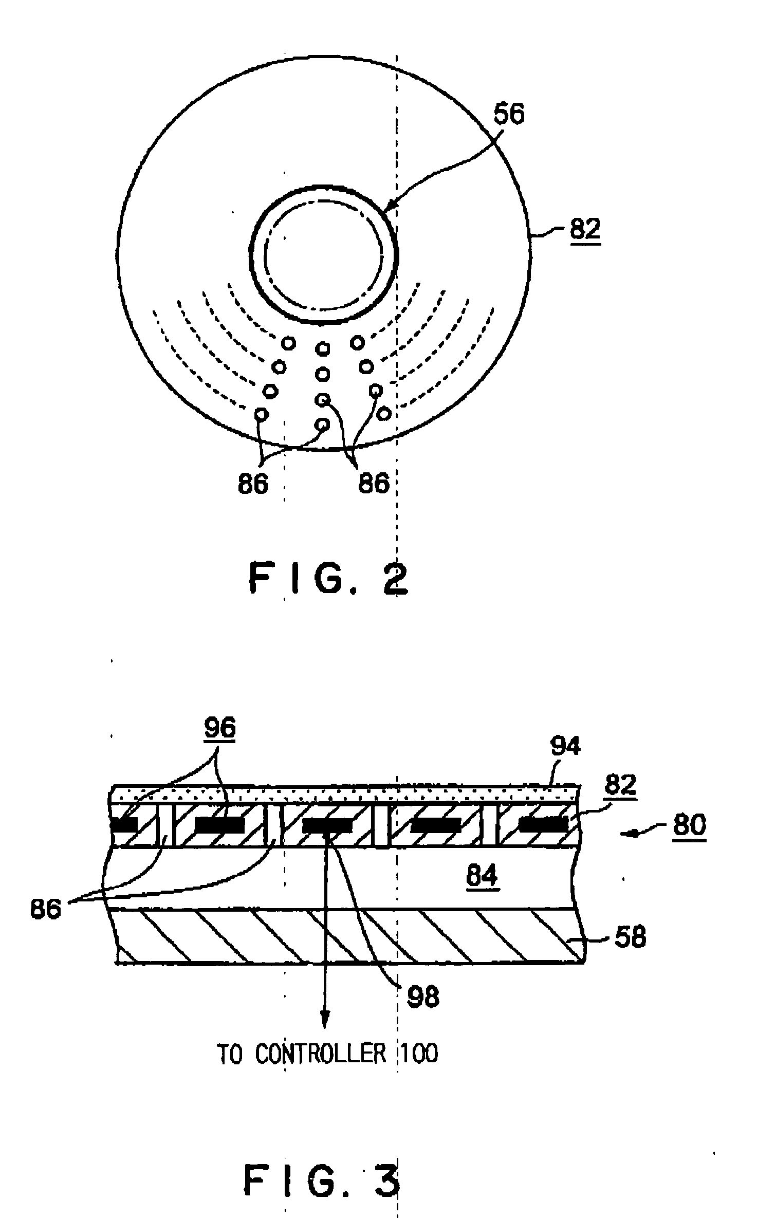
[0103] A first invention will be explained firstly. FIG. 1 is a cross-sectional block diagram showing the first invention of the processing system having a gas supply system according to the present invention, FIG. 2 is a plan view showing a gas injection plate, and FIG. 3 is an enlarged, partial, cross-sectional view showing a first carrier gas supply means at the bottom of a material reservoir tank.

[0104] As shown in FIG. 1, this processing system 20 mainly comprises a processing apparatus 22 for directly performing predetermined processing onto an object to be processed such as a semiconductor wafer, and a gas supply system 24 for supplying gas necessary for the aforementioned processing into the processing apparatus 22.

[0105] The processing apparatus 22 has a processing vessel ...


PUM

PropertyMeasurementUnit
internal diameteraaaaaaaaaa
thicknessaaaaaaaaaa
diameteraaaaaaaaaa

Abstract

A processing system that can supply a material gas produced inside a material reservoir tank into a processing apparatus while generating almost no pressure loss is provided.
In a processing system comprising: a processing apparatus including a gas injection means 42 for injecting a specific material gas into a processing vessel 26 in order to provide specific processing to an object to be processed W, said material gas being produced from a metallic compound material M with low vapor pressure; and a gas supply system 24 for supplying said specific material gas to said gas injection means, said gas injection means is a shower head portion and said gas supply system provides: a gas passage 56 extending upwardly from said showerhead portion; a material reservoir tank 58 attached to the upper-end portion of said gas passage for containing said metallic compound material therein; and an open/close valve 60 for opening/closing said gas passage.

Description

FIELD OF INVENTION [0001] The present invention relates to a processing system that provides specific processing to an object to be processed such as a semiconductor wafer and a gas supply line that supplies processing gas. BACKGROUND OF INVENTION [0002] In general manufacturing; of semiconductor devices, repetitious processes of film formation and pattern etching are provided on semiconductor wafers to manufacture intended devices. Every year the demands particularly for high specifications of the film formation technique are growing as semiconductor devices became highly densified and integrated, and further reduction in the thickness of the film has been required to form quite thin oxide films, such as insulating films and gate-insulating films in a capacitor in the device for example, in which high insulating ability is also required. [0003] Silicon oxide films and silicon nitride films can be used for these insulating films, but more metal oxide films are recently chosen as mat...

Claims


Application Information

Patent Timeline
Patent Type & Authority Applications(United States)
IPC IPC(8): C23F1/00C23C16/448C23C16/455H01L21/00H01L21/285H01L21/31
CPCH01L21/67017C23C16/4481Y10T137/0324C23C16/448H01L21/31
Inventor KASAI, SHIGERUTANAKA, SUMISAITO, TETSUYAYAMAMOTO, NORIHIKOYANAGITANI, KENICHI
Owner TOKYO ELECTRON LTD
Why Eureka
Try Eureka