
Methods of fabricating transistors including dielectrically-supported gate electrodes and related devices

a dielectric and gate electrode technology, applied in transistors, material analysis, instruments, etc., can solve the problems of affecting device operation, gaps may form between the edges of dielectric and gate electrode, and more familiar semiconductor materials may not be well suited for higher power and/or high frequency applications, so as to reduce the gate-to-drain and/or gate-to-source capacitance of the device

Active Publication Date: 2007-07-19
CREE INC
View PDF99 Cites 180 Cited by
  • Summary
  • Abstract
  • Description
  • Claims
  • Application Information

AI Technical Summary

Benefits of technology

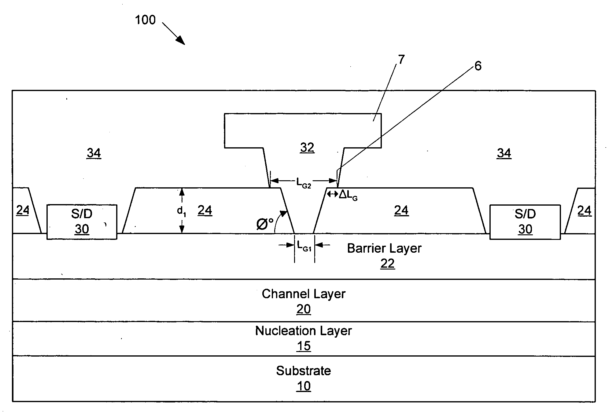
[0013]In some embodiments, the dielectric layer may have a thickness greater than that of the protective layer. For example, the dielectric layer may have a thickness of about 500 Angstroms (Å) to about 3000 Å, and the protective layer may have a thickness of about 200 Å to about 2000 Å. The thickness and / or the dielectric index of the dielectric layer may be sufficient to reduce the gate-to-drain and / or gate-to-source capacitance of the device.
[0028]In still other embodiments, the dielectric layer may have a thickness greater than that of the protective layer. For example, the dielectric layer may have a thickness of about 500 Angstroms (Å) to about 3000 Å, and the protective layer may have a thickness of about 200 Å to about 2000 Å. The thickness and / or the dielectric index of the dielectric layer may be sufficient to reduce the gate-to-drain and / or gate-to-source capacitance of the device.

Problems solved by technology

However, these more familiar semiconductor materials may not be well suited for higher power and / or high frequency applications, for example, due to their relatively small bandgaps (e.g., 1.12 eV for Si and 1.42 for GaAs at room temperature) and / or relatively small breakdown voltages.
However, in such conventional methods, gaps may be formed between the edges of the dielectric and the gate electrode, due to isotropy of the dielectric etch.
This may be detrimental to device operation, as the unpassivated semiconductor surface exposed by the gap may cause current collapse and / or drift in the device.
In addition, although a passivation layer may be formed in the gap after formation of the gate, the passivation properties of such a post-gate passivation layer may be inferior to that of the initial pre-gate dielectric.
This may be due to the fact that the pre-gate dielectric can be formed at relatively high temperatures, which may not be feasible once the gate metallization has been deposited.
However, because portions of the dielectric may be sandwiched between the sidelobes and the active channel, gate-drain capacitance (cgd) and / or gate-source capacitance (cgs) may be increased, which may detrimentally affect device performance.

Method used


Image

  • Methods of fabricating transistors including dielectrically-supported gate electrodes and related devices
  • Methods of fabricating transistors including dielectrically-supported gate electrodes and related devices
  • Methods of fabricating transistors including dielectrically-supported gate electrodes and related devices

Examples


Embodiment Construction

[0037]The present invention now will be described more fully hereinafter with reference to the accompanying drawings, in which embodiments of the invention are shown. However, this invention should not be construed as limited to the embodiments set forth herein. Rather, these embodiments are provided so that this disclosure will be thorough and complete, and will fully convey the scope of the invention to those skilled in the art. In the drawings, the thickness of layers and regions are exaggerated for clarity. Like numbers refer to like elements throughout.

[0038]It will be understood that when an element such as a layer, region or substrate is referred to as being “on” or extending “onto” another element, it can be directly on or extend directly onto the other element or intervening elements may also be present. In contrast, when an element is referred to as being “directly on” or extending “directly onto” another element, there are no intervening elements present. It will also be ...


PUM


Abstract

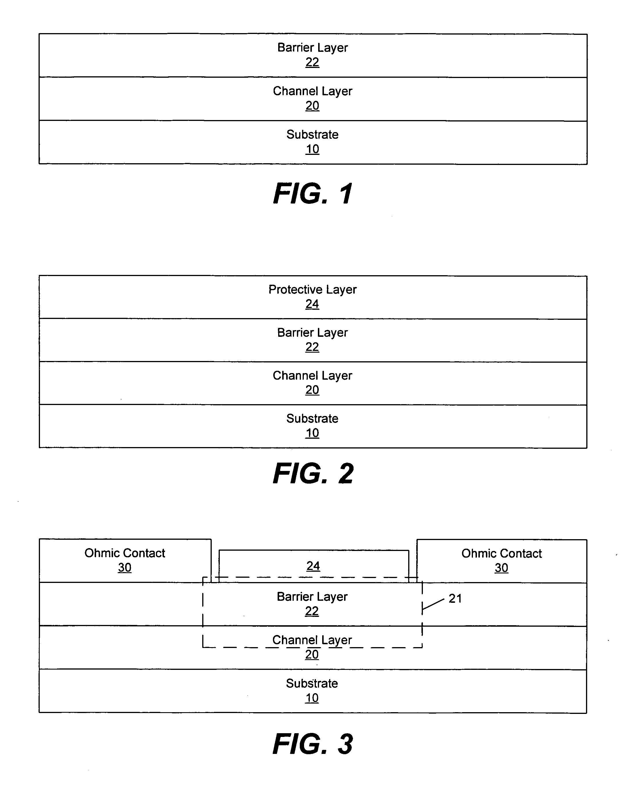
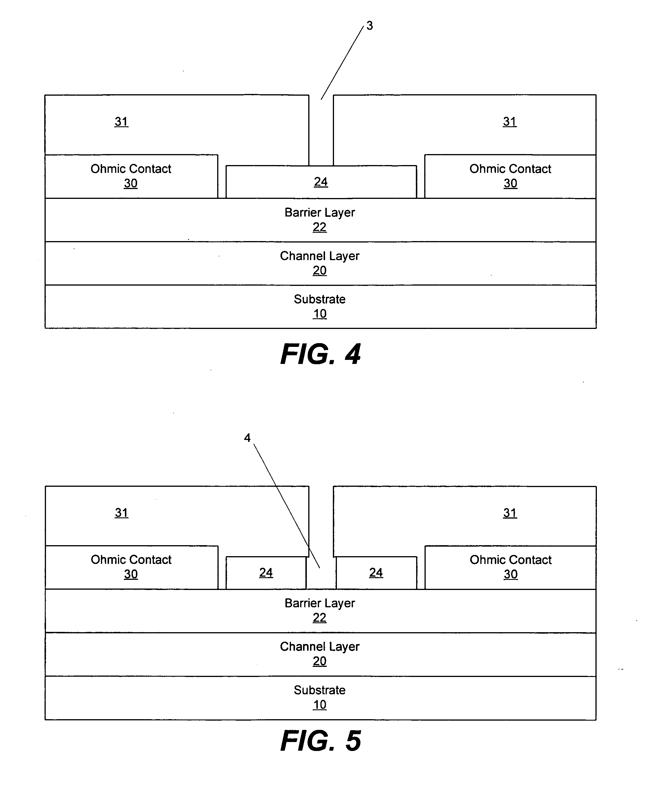
Transistors are fabricated by forming a protective layer having a first opening extending therethrough on a substrate, forming a dielectric layer on the protective layer having a second opening extending therethrough that is wider than the first opening, and forming a gate electrode in the first and second openings. A first portion of the gate electrode laterally extends on surface portions of the protective layer outside the first opening, and a second portion of the gate electrode is spaced apart from the protective layer and laterally extends beyond the first portion on portions of the dielectric layer outside the second opening. Related devices and fabrication methods are also discussed.

Description

CROSS-REFERENCE TO RELATED APPLICATION[0001]The present application is a continuation-in-part of U.S. patent application Ser. No. 11 / 333,726 filed Jan. 17, 2006, entitled METHODS OF FABRICATING TRANSISTORS INCLUDING SUPPORTED GATE ELECTRODES AND RELATED DEVICES, the disclosure of which is hereby incorporated by reference as if set forth fully herein.FIELD OF THE INVENTION[0002]The present invention relates to semiconductor devices, and, more particularly, to methods of fabricating transistors and related devices.BACKGROUND OF THE INVENTION[0003]Materials such as silicon (Si) and gallium arsenide (GaAs) have found wide application in semiconductor devices for lower power and, in the case of Si, lower frequency applications. However, these more familiar semiconductor materials may not be well suited for higher power and / or high frequency applications, for example, due to their relatively small bandgaps (e.g., 1.12 eV for Si and 1.42 for GaAs at room temperature) and / or relatively smal...

Claims


Application Information

Patent Timeline
IPC IPC(8): H01L29/80H01L21/338
CPCH01L29/2003H01L29/42312H01L29/7787H01L29/66462H01L29/66431H01L29/401H01L29/402
Inventor SMITH, RICHARD PETERSHEPPARD, SCOTT T.
Owner CREE INC
Learn More