Remote cholesteric display

a technology of cholesteric display and remote control, which is applied in the field of remote cholesteric display, can solve the problems of low power, difficult or impossible observation of many information on the small display of pda, and the recent achievement of drapable liquid crystal display, etc., and achieve the effect of reducing the cost of fabricating the display and conserving spa

Inactive Publication Date: 2007-07-19
MANNING VENTURES
View PDF61 Cites 54 Cited by
  • Summary
  • Abstract
  • Description
  • Claims
  • Application Information

AI Technical Summary

Benefits of technology

[0022] Moreover, the present invention is unique in that the layer of photovoltaic material of the solar cell can itself form a single substrate of the display, whereby the display components including a dispersion layer of cholesteric liquid crystal material in a polymer matrix, and electrodes on either side of the dispersion layer (e.g., electrodes formed of conductive polymer) can be printed, coated, laminated or formed and transferred, onto the photovoltaic layer without a substrate between the liquid crystal layer and the photovoltaic layer. The term “substrate” as used in this disclosure has the meaning provided in the 11 / 046,487 application. In this design, the solar cell becomes a component of the cholesteric liquid crystal display, which conserves space and reduces the cost of fabricating the display.

Problems solved by technology

Much of this information may be difficult or impossible to observe on the small display of the PDA.
However, a low power, drapable liquid crystal display has only recently been achieved in one of the Related Applications listed above.

Method used


Image

  • Remote cholesteric display
  • Remote cholesteric display
  • Remote cholesteric display

Examples


Embodiment Construction

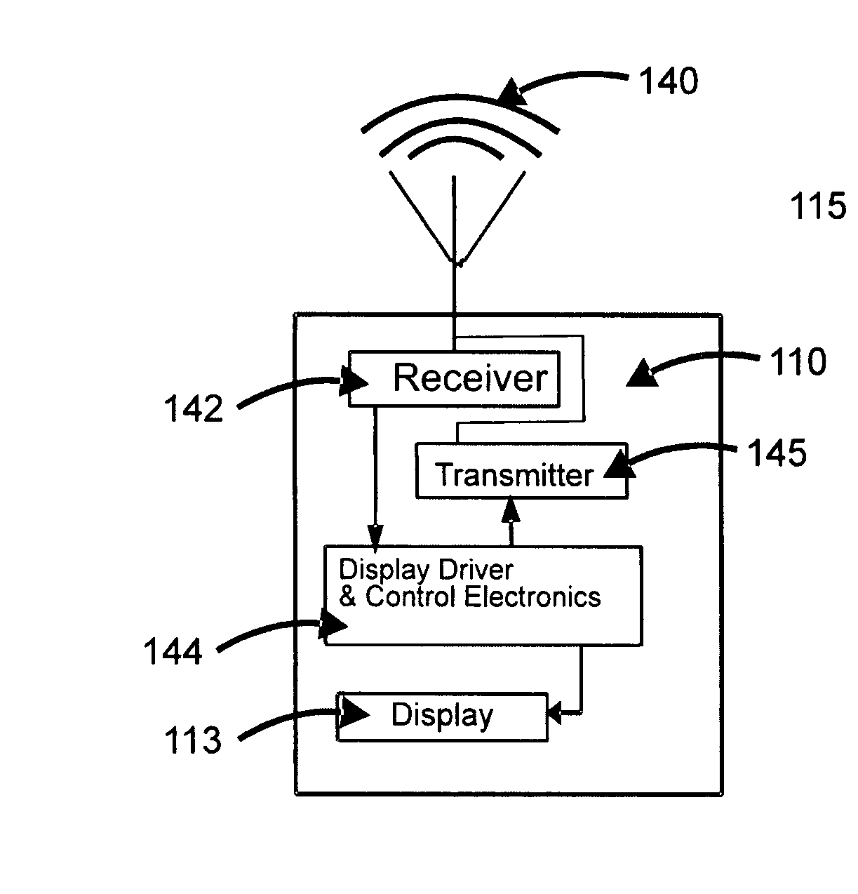
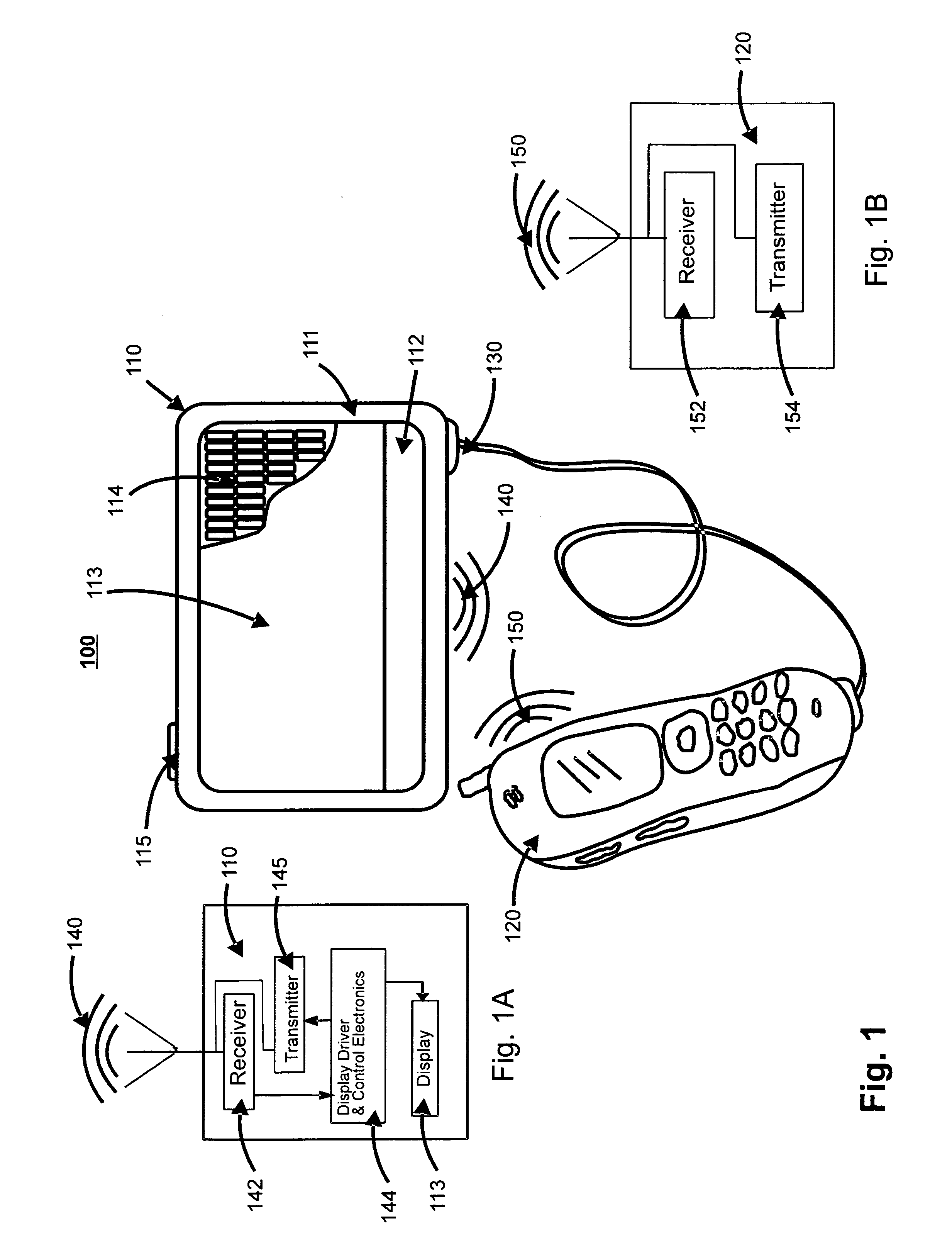
[0040] The present invention features an apparatus that includes a remote display device with a larger screen than an associated handheld or otherwise portable communications device. FIG. 1 shows the inventive apparatus 100 including a handheld remote display device 110 with a wireless connection 140 and 150, to a smaller portable electronic communications device, illustrated here as a cellular telephone 120. The device 120 is attached to the remote display 110 through an optional cable 130 that enables power to be supplied to the device 120.

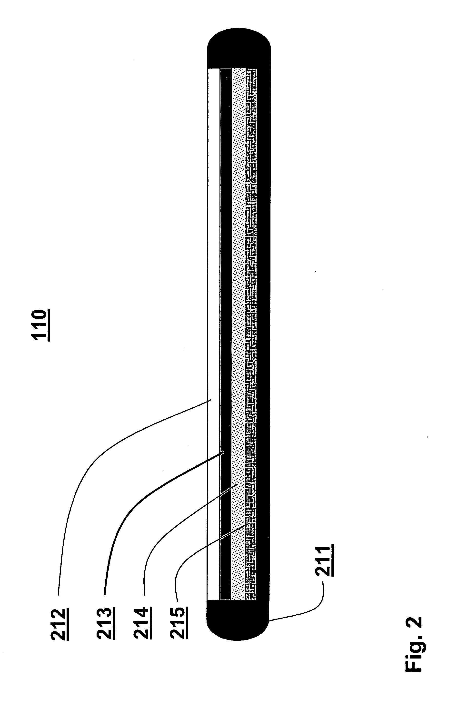
[0041] The remote display device 110 includes a cholesteric reflective display 113 adapted to display images such as text messages, documents, calendars, graphics, photographs or other information supplied by the electronic device 120. Device 120 can be a cellular telephone (“cell phone”), camera, electronic book (“e-book”), personal digital assistant (“PDA”), MP3 player, handheld computer, radio, “walkie-talkie,” global positioning system (GPS...


PUM


Abstract

The present invention enables a user of a portable electronic communications device such as a cell phone to view information on a larger remote reflective cholesteric display. The portable communications device may connect with the remote display by wire or wirelessly. The remote display is separate from the portable communications device but can interact with it. The remote display receives and/or receives and sends information relative to the portable communications device. This information can include e-mail text and graphics. The remote display, being a bistable cholesteric liquid crystal display, possesses low power requirements unmatched by other display technologies. Moreover, the remote display can serve a dual purpose of displaying images and collecting solar power whereby a photovoltaic material behind the display generates electrical energy from light incident on the cholesteric liquid crystal material, which may be used not only to power the remote display but also the portable communications device. This may result in a completely self-powered remote display and associated portable communications device. The solar cell itself can be a component of the display. A display having only a single substrate may employ the solar cell as the substrate. A dispersion layer comprised of cholesteric liquid crystal material dispersed in a polymer matrix, may be disposed over the substrate. Another aspect of the invention features a drapable remote bistable cholesteric display.

Description

BACKGROUND [0001] Handheld devices such as cell telephones and personal digital assistants (PDAs) are limited by the relatively small size of the display screen. The handheld device is generally small and compact. Correspondingly, the size of the display screen is also small. Space is only available on the screen to display abbreviated or simplistic content. For example, a cellular telephone that receives an e-mail is only capable of displaying a few words. It would be impossible to display an entire Web page on these handheld devices. On the other hand, it is inconvenient to carry around and operate a laptop computer for the benefit of its larger display. Most handheld devices are capable of supplying data to display more information if a larger display were available. As a result, recently a number of solutions have been proposed. [0002] U.S. Pat. No. 6,574,488 discloses a terminal that is portable and detachable from a base (such as a cell phone). The terminal has a separate, lar...

Claims


Application Information

Patent Timeline
Patent Type & Authority Applications(United States)
IPC IPC(8): G09G3/36
CPCG06F3/147
Inventor MANNING, WILLIAM
Owner MANNING VENTURES
Why Eureka
Try Eureka