Rotor hub fairing system for a counter-rotating, coaxial rotor system

a rotor hub and coaxial technology, applied in the direction of rotors, marine propulsion, vessel construction, etc., can solve the problems of increasing the drag of the rotor system for rotary wing aircraft, and the relative power penalty, so as to reduce the total drag of the rotor hub fairing system, the effect of reducing the overall drag and reducing the drag of the individual fairing components

Active Publication Date: 2007-07-19
SIKORSKY AIRCRAFT CORP
View PDF24 Cites 31 Cited by
  • Summary
  • Abstract
  • Description
  • Claims
  • Application Information

AI Technical Summary

Benefits of technology

[0006] A rotor hub fairing system for a dual, counter-rotating, coaxial rotor system according to the present invention generally includes an upper hub fairing, a lower hub fairing and a shaft fairing therebetween. The rotor hub fairing system is a system by which overall drag is reduced on a system level. That is, although the drag on an individual fairing component may be increased, through overall system design, the total drag of the rotor hub fairing system is reduced.
[0007] Applicants have discovered a plurality of different features for reducing the overall drag associated with the main rotor. Specifically, the Applicants have discovered that by fairing shaping, i.e., sizing and shaping the upper and lower hub fairings and the interconnecting shaft fairing to reduce the flow separation and interference drag, overall rotor hub drag can be decreased. That is, Applicants have discovered that by increasing the relative size of the shaft faring, overall drag on the rotor hub fairing system can be reduced even though the drag associated with the shaft fairing component is increased. This is because the thicker shaft fairing provides a positive effect on the upper hub fairing and the lower hub fairing by reducing flow separation on these components and exposed surface area on these components. Furthermore, the Applicants have further discovered that overall drag on the rotor hub fairing system can be reduced by reducing the diameter of the upper and lower hub fairings, even though the thickness ratio (ratio of thickness to diameter) of the fairing may increase. Thus, by increasing the size of the shaft fairing and by decreasing the size of the upper and lower hub fairings, the Applicants discovered that the overall total drag of the rotor hub fairing system is reduced.
[0008] Applicants have also discovered that overall drag on the rotor hub fairing system can be decreased by incorporating at least one airfoil member, such as a splitter or vane, which extends generally transverse to said shaft fairing. That is, Applicants discovered that by incorporating flow splitters and vanes air flow is encouraged to remain attached to the fairing system, which in turn causes overall rotor hub fairing drag to be reduced.

Problems solved by technology

The rotor system drag increases for a rotary wing aircraft having a counter-rotating, coaxial rotor system primarily due to the additional rotor hub and the interconnecting main rotor shaft assembly between the upper and lower rotor systems.
For high-speed rotary wing aircraft, the increased drag resulting from the counter-rotating, coaxial rotor system may result in a relatively significant power penalty.

Method used


Image

  • Rotor hub fairing system for a counter-rotating, coaxial rotor system
  • Rotor hub fairing system for a counter-rotating, coaxial rotor system
  • Rotor hub fairing system for a counter-rotating, coaxial rotor system

Examples


Embodiment Construction

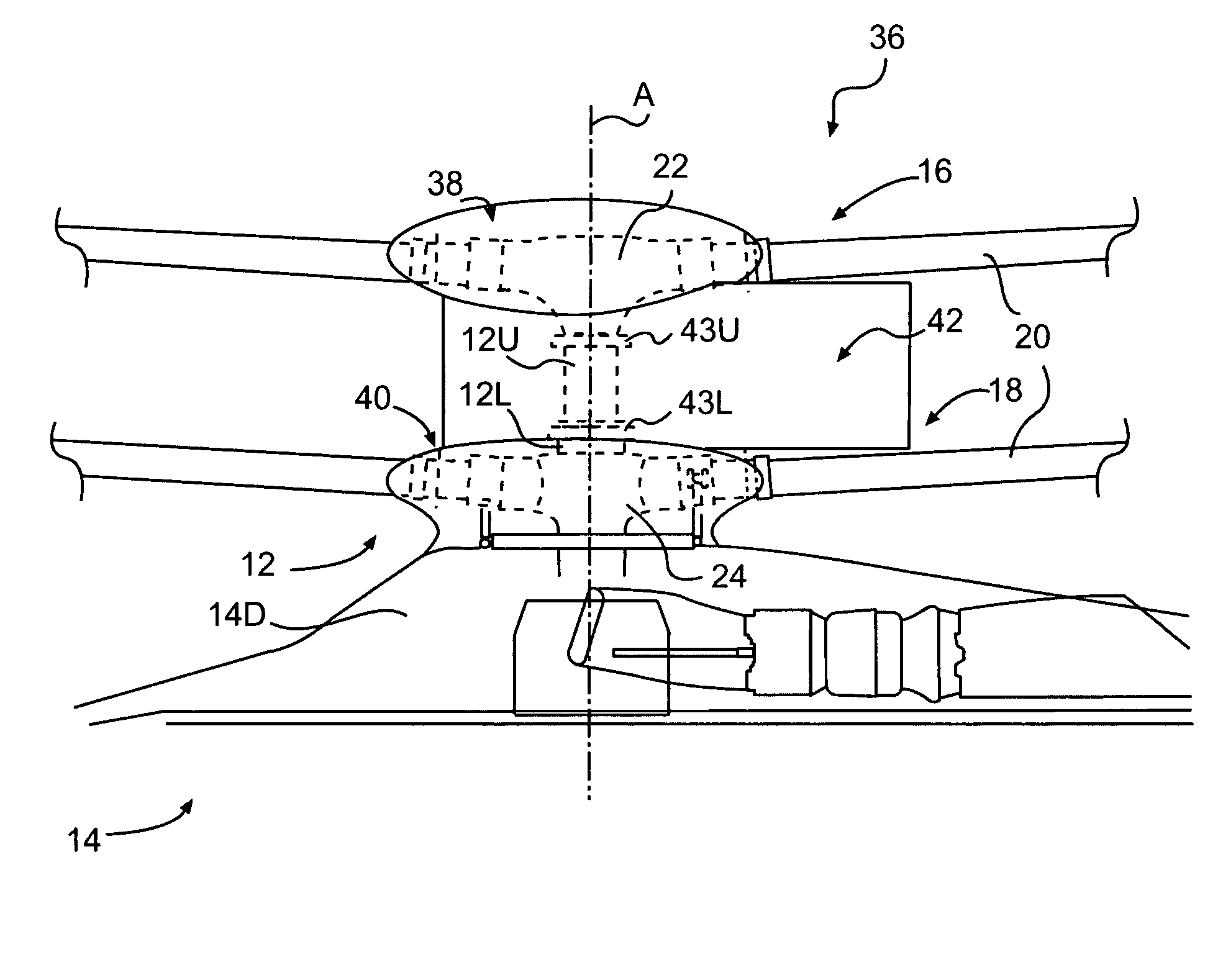
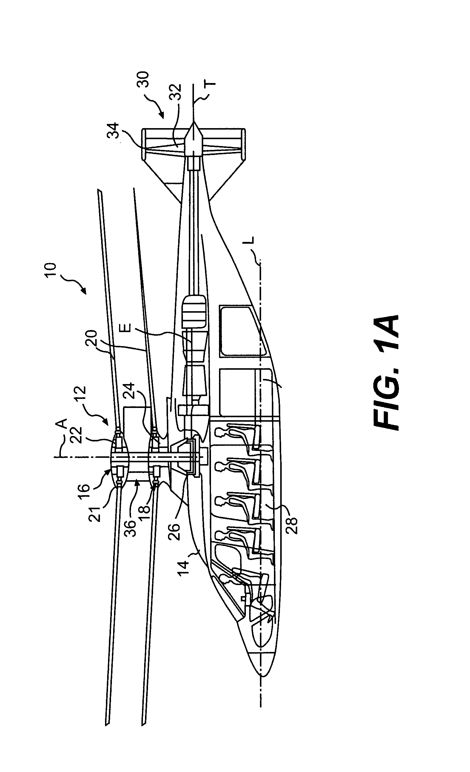
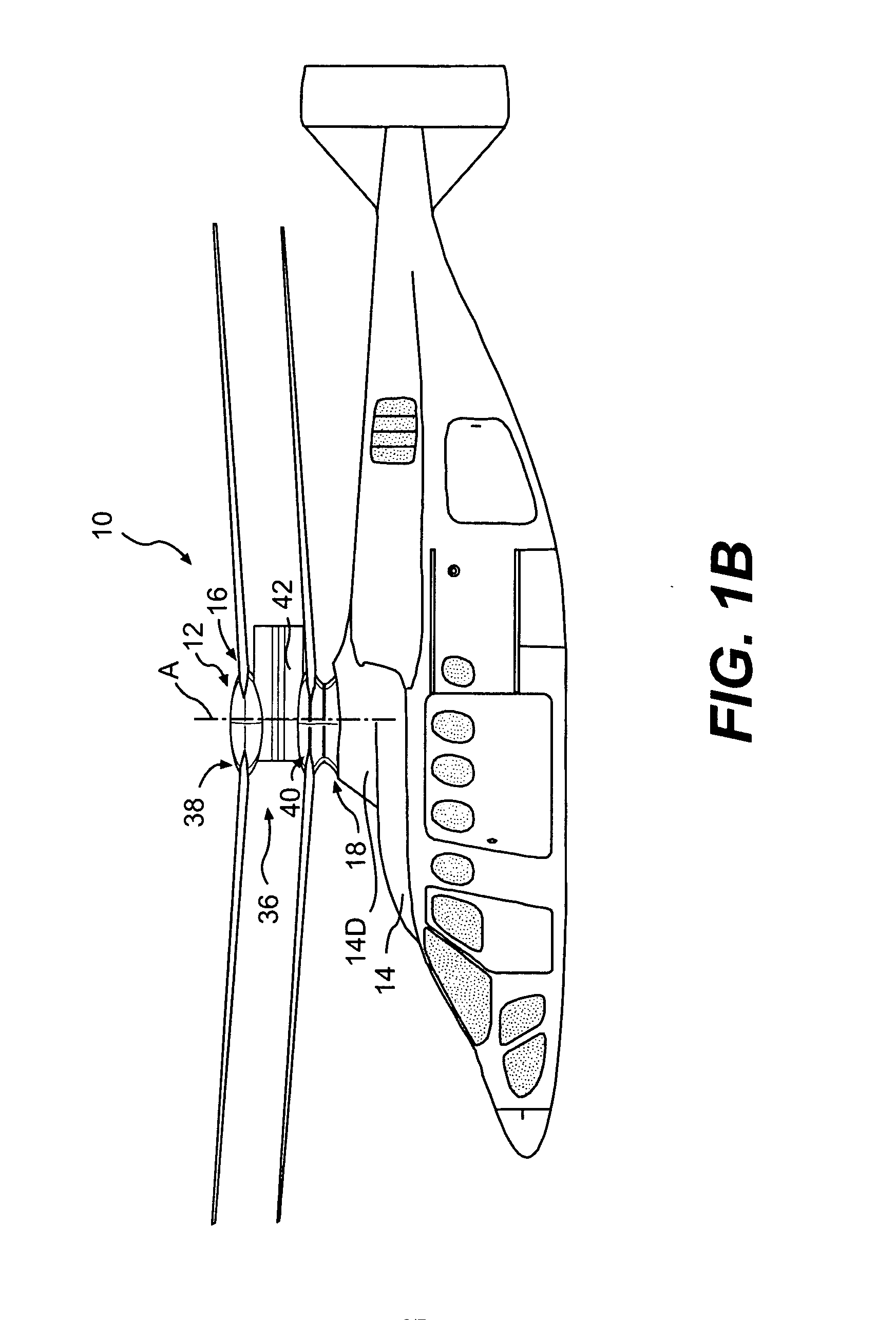
[0052]FIGS. 1A and 1B illustrate an exemplary vertical takeoff and landing (VTOL) rotary-wing aircraft 10 having a dual, counter-rotating, coaxial rotor system 12. The aircraft 10 includes an airframe 14 which supports the dual, counter rotating, coaxial rotor system 12 as well as a translational thrust system 30 which provides translational thrust generally parallel to an aircraft longitudinal axis L. Although a particular aircraft configuration is illustrated in the disclosed embodiment, other VTOL aircrafts may also benefit from the present invention.

[0053] The dual, counter-rotating, coaxial rotor system 12 includes an upper rotor system 16 and a lower rotor system 18. Each rotor system 16, 18 includes a plurality of rotor blades 20 mounted to a rotor hub 22, 24 for rotation about a rotor axis of rotation A. A plurality of the main rotor blades 20 extend outward from the hub assemblies 22, 24 and are connected thereto in any manner known to one of ordinary skill in the art (sch...


PUM


Abstract

A rotor hub fairing system includes an upper hub fairing, a lower hub fairing and a shaft fairing therebetween. The rotor hub fairing system reduces the total drag on a dual, counter-rotating, coaxial rotor system. Other aerodynamic structures may be mounted to the shaft fairing, hub fairings and airframe to facilitate flow around the upper and lower hub fairings to reduce flow separation and drag.

Description

[0001] The present application is a continuation-in-part application that claims priority to U.S. patent application Ser. No. 11 / 141,246, filed May 31, 2005.BACKGROUND OF THE INVENTION [0002] The present invention is directed to a rotor hub fairing system, and more particularly, to a rotor hub fairing system which reduces overall drag for a high-speed rotary-wing aircraft having a counter-rotating, coaxial rotor system. [0003] Typically, the aerodynamic drag associated with a rotor system of a rotary wing aircraft is a significant portion of the overall aircraft drag, typically 25% to 30% for conventional single-rotor helicopters. The rotor system drag increases for a rotary wing aircraft having a counter-rotating, coaxial rotor system primarily due to the additional rotor hub and the interconnecting main rotor shaft assembly between the upper and lower rotor systems. For high-speed rotary wing aircraft, the increased drag resulting from the counter-rotating, coaxial rotor system ma...

Claims


Application Information

Patent Timeline
Patent Type & Authority Applications(United States)
IPC IPC(8): B64C27/50
CPCB64C1/00B64C7/00B64C27/04B64C27/20B64C27/12B64C27/14B64C27/10
Inventor BERTOLOTTI, FABIO P.SCOTT, MARK W.WAKE, BRIAN E.EGOLF, T. ALANMCCORMICK, DUANE C.USTA, EBRUOCHS, STUART S.
Owner SIKORSKY AIRCRAFT CORP
Why Eureka
Try Eureka