Magnetic sputter targets manufactured using directional solidification

a directional solidification and magnetic sputter technology, applied in the field of sputter targets, can solve the problems of ingot cracking, limited effectiveness of sputter targets composed of low-ductility alloys, etc., and achieve the effect of improving microstructural homogeneity and higher p

Inactive Publication Date: 2007-07-26
HERAEUS INC
View PDF13 Cites 9 Cited by
  • Summary
  • Abstract
  • Description
  • Claims
  • Application Information

AI Technical Summary

Benefits of technology

[0006] In accordance with the present invention, a sputter target is provided that has improved microstructural homogeneity and higher PTF than was previously possible. The sputter target is formed by directionally solidifying a metal alloy at near-equilibrium temperature conditions by withdrawing the metal alloy at a first rate through a temperature gradient. A sputter target thus manufactured has a single substantially homogenous microstructural zone substantially across its entire thickness.

Problems solved by technology

These techniques are limited in effectiveness due to the increased manufacturing time required by thermo-mechanical working processes, such as rolling and heat treatment.
Moreover, these processes may significantly limit the yield of sputter targets composed of low-ductility alloys, as the risk of ingot cracking during the thermo-mechanical working is higher with these difficult-to-roll alloys.
Further, any deviation from the rolling and heat treatment process window can result in un-precedent microstructural non-homogeneity across the target thickness (e.g., along the sputter direction).
The techniques to improve PTF made by standard solidification practices followed by thermo-mechanical working discussed above suffer from drawbacks of high expense, long processing time, and low yield.

Method used


Image

  • Magnetic sputter targets manufactured using directional solidification
  • Magnetic sputter targets manufactured using directional solidification
  • Magnetic sputter targets manufactured using directional solidification

Examples


Embodiment Construction

[0022] In the following detailed description, numerous specific details are set forth to provide a full understanding of the present invention. It will be obvious, however, to one ordinarily skilled in the art that the present invention may be practiced without some of these specific details. In other instances, well-known structures and techniques have not been shown in detail not to obscure the present invention.

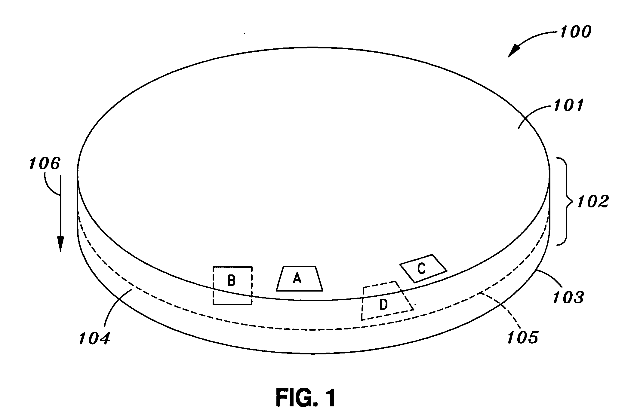
[0023] Referring to FIG. 1, a sputter target in accordance with one embodiment of the present invention is illustrated. A sputter target 100 includes a metal alloy. The metal alloy has a target surface such as a target surface 101, a rear surface such as a rear surface 103, and a side surface such as a side surface 104. The metal alloy further has a thickness such as thickness 102 between target surface 101 and rear surface 103, and further has a thickness direction 106 substantially along the thickness 102. Target surface 101 is an outer surface of the metal alloy and is...


PUM

PropertyMeasurementUnit
areaaaaaaaaaaa
angleaaaaaaaaaa
thicknessaaaaaaaaaa

Abstract

A sputter target includes a metal alloy having a target surface, a rear surface and a thickness between the target and rear surfaces. The target surface and rear surface are outer surfaces of the metal alloy. The metal alloy has a thickness direction substantially along the thickness. The target surface is substantially normal to the thickness direction. The metal alloy has a single substantially homogenous microstructural zone across substantially the entire thickness. The metal alloy further includes dendrites. The dendrites at the target surface are oriented along substantially one direction, and the dendrites at a center plane of the metal alloy are oriented along substantially the same one direction. A sputter target may include a metal alloy which is a cobalt (Co) based, and may have a [0001] hexagonal close-packing (HCP) direction oriented substantially normal to the target surface. The sputter target may be formed by directional solidification at near-equilibrium temperature conditions by withdrawing the metal alloy at a first rate through a temperature gradient. The sputter target is for forming one or more magnetic layers on a substrate for, among other purposes, data storage.

Description

FIELD OF THE INVENTION [0001] The present invention generally relates to sputter targets and, in particular, relates to sputter targets with improved microstructural homogeneity and pass through flux (“PTF”), and to the products produced therefrom such as thin film magnetic media. BACKGROUND OF THE INVENTION [0002] Cathodic sputtering processes are widely used for the deposition of thin films of material onto desired substrates. In particular, thin film magnetic media can be manufactured using a cathodic sputtering process. Concomitant with the ever increasing demand for improved magnetic storage media has been an increasing need for thin films of magnetic media with improved magnetic characteristics and uniformity. To obtain thin films with these desired attributes, it is necessary to use sputter targets with improved microstructural homogeneity. [0003] One approach to improving the microstructural homogeneity of sputter targets is a process using vacuum induction melting and ingot...

Claims


Application Information

Patent Timeline
Patent Type & Authority Applications(United States)
IPC IPC(8): C22C19/07
CPCB22D27/045C23C14/3414C22C19/07C22C19/007C23C14/3407
Inventor KUNKEL, BERNDLONG, DAVIDZIANI, ABDELOUAHABDAS, ANIRBANHUI, JUN
Owner HERAEUS INC
Why Eureka
Try Eureka