
Method for synchronizing an image data source and a resonant mirror system to generate images

a resonant mirror and image data technology, applied in the field of video display and laser printer systems, can solve the problems of reducing the beam envelope, reducing the amplitude of the beam sweep, and complex problems, so as to reduce the cost and complexity of the system, and eliminate the effect of sensors

Active Publication Date: 2007-07-26
TEXAS INSTR INC
View PDF3 Cites 4 Cited by
  • Summary
  • Abstract
  • Description
  • Claims
  • Application Information

AI Technical Summary

Benefits of technology

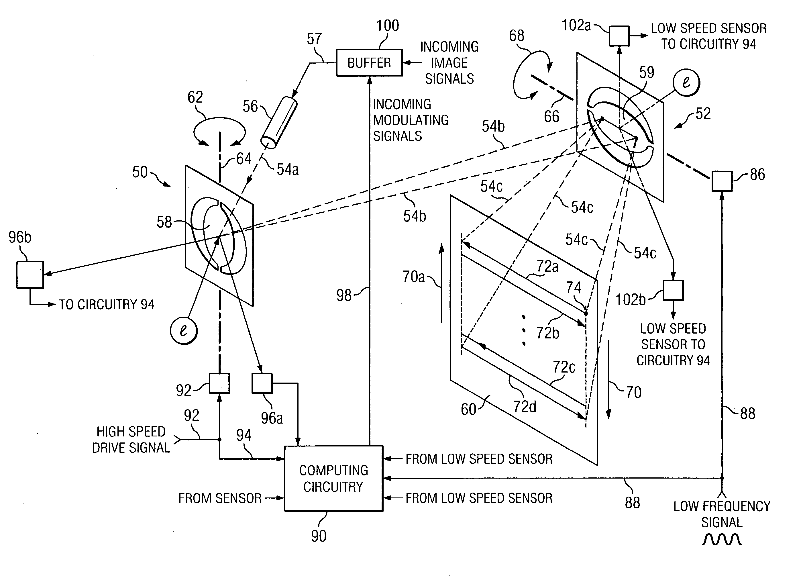
[0013] According to another embodiment, the step of generating the low speed cyclic drive signal may comprise repetitive generation of a series of discrete values that in turn generate one cycle of the drive signal, and the step of adjusting the peak portions comprises increasing the number of discrete values making up the peak portion that drives or positions the low frequency mirror. These additional discrete values may expand the peak portion (i.e. increase the cycle time). Alternately, in some situations, the number of discrete values may be decreased to compress the peak portion (i.e. decrease cycle time) of the drive signal. Such increasing or decreasing the peak portion of the low frequency drive signals may be accomplished according to one embodiment of the invention by generating a “surplus” or excess number of discrete values than are required for one complete cycle time. All of the discrete values are stored in a circular buffer. The circular buffer creates the cyclic motion of the drive signal. The required time to complete the turn around or peak portion of the drive signal for each cycle may then be provided by positioning the restart or wrap around pointer to include the proper number of the surplus discrete values.
[0015] In one embodiment, the “arming” signal is based on sensors, which monitor the position of the low-speed mirror. Alternately, in another embodiment, the position is inferred based on the driving waveform, which will have a reasonably constant phase lead relative to the actual position. This embodiment may allow the elimination of sensors resulting in lower system cost and complexity. Due to the variation in phase between the high speed mirror drive signal and mirror position, a sensor will typically be required to generate the “trigger” signals.

Problems solved by technology

Unfortunately, the problem is more complex than that.
At the same time, however, the high frequency mirror must run or oscillate at substantially its resonant frequency, since driving a high-Q mirror at a frequency only slightly different than the resonant frequency will result in a significant decrease in the amplitude of the beam sweep (i.e. reduce the beam envelope).
This would cause a significant and unacceptable compression of the image on the display.
Also of course, if complete image frames are lost or dropped, artifacts in the display would clearly be observed.
Further, the problems discussed above are even further complicated if there has been some degradation of the video signal.
For example, if the source of the video signals is a VCR, one common problem such as stretching of the VCR tape could vary the incoming frame rate, which must also be dealt with.

Method used


Image

  • Method for synchronizing an image data source and a resonant mirror system to generate images
  • Method for synchronizing an image data source and a resonant mirror system to generate images
  • Method for synchronizing an image data source and a resonant mirror system to generate images

Examples


Embodiment Construction

[0027] The making and using of the presently preferred embodiments are discussed in detail below. It should be appreciated, however, that the present invention provides many applicable inventive concepts that can be embodied in a wide variety of specific contexts. The specific embodiments discussed are merely illustrative of specific ways to make and use the invention, and do not limit the scope of the invention.

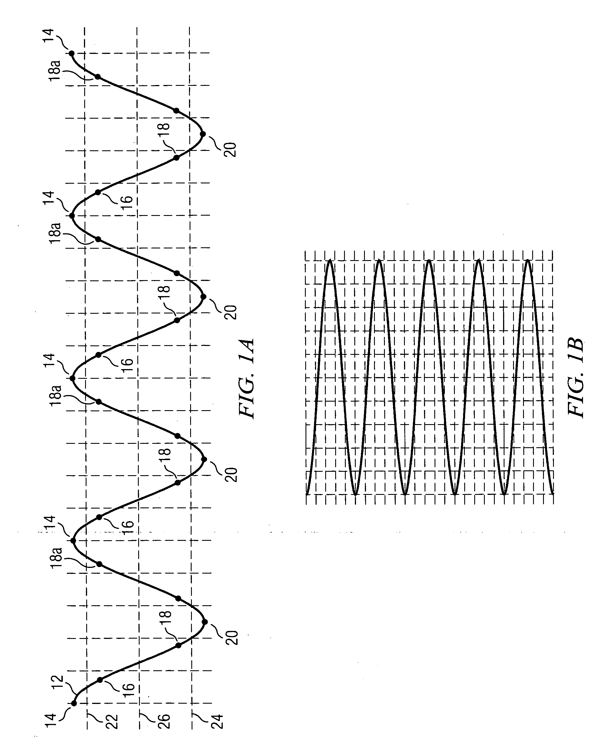
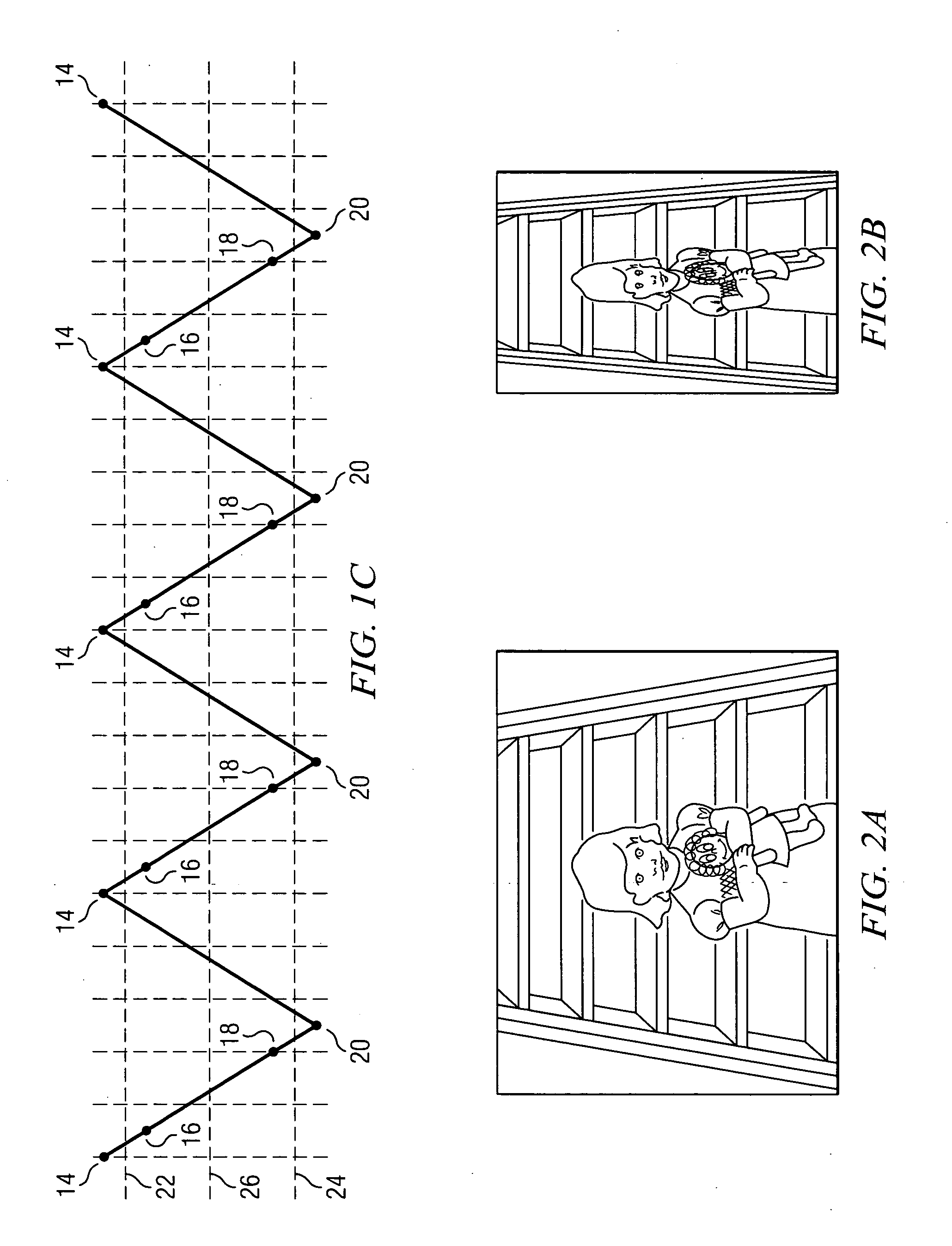
[0028] Referring now to FIGS. 1A and 1B along with prior art FIG. 6, there is illustrated the interaction of a high speed horizontal scanning drive signal and a low speed (vertical) or scan line positioning signal used to control a prior art electronic display formed by a raster scan, such as for example a CRT display. The terms “horizontal”, used with respect to scanning drive signals, and “vertical”, used with respect to the beam positioning signals are for convenience and explanation purposes only, and it will be appreciated by those skilled in the art that the scan line...


PUM


Abstract

System and method for synchronizing the low speed mirror movement of a mirror display system with incoming frame or video signals, and synchronizing buffered lines of video data to the independently oscillating scanning mirror. According to one embodiment of the invention, the peak portions of the low speed cyclic drive signal are synchronized with the incoming frames of video by compressing or expanding the peak portion or turn around portion so that each video frame begins at the same location on the display screen. The actual position of the high frequency mirror is determined by sensors and a “trigger” signal is generated to distribute the signals for each scan line such that the scan lines are properly positioned on the display.

Description

TECHNICAL FIELD [0001] The present invention relates to video display and laser printer systems comprising a high speed scanning mirror for generating scan or image lines to produce an image and a method of synchronizing a data stream that represents the scan lines with the high speed mirror. [0002] When used with a video display, the invention further relates to synchronizing a low frequency mirror that moves the modulated light beam substantially orthogonal to the movement of the high speed mirror to position the scan lines. More particularly, the invention relates to synchronizing the movement of the low frequency mirror with the start point of an image frame, and properly spacing each of the scan lines. [0003] When used with a laser printer, the high speed mirror operates the same as when used with a video display. More specifically, the stream of data representing a scan line is synchronized with the high speed mirror. However, the start point of a printed page is synchronized ...

Claims


Application Information

Patent Timeline
Patent Type & Authority Applications(United States)
IPC IPC(8): H04N1/04
CPCG02B26/101G02B26/105H04N1/053H04N2201/04789H04N3/08H04N9/3129H04N2201/04755H04N1/113
Inventor OETTINGER, ERIC GREGORYNOXON, JAMES EUGENE
Owner TEXAS INSTR INC
Learn More