Desiccant sealing arrangement for OLED devices

a sealing arrangement and oled technology, applied in the direction of semiconductor/solid-state device manufacturing, basic electric elements, electric apparatus, etc., can solve the problems of low level, low moisture capacity of molecular sieve materials, and inability to achieve low levels, so as to reduce moisture permeability and reduce moisture permeability

Inactive Publication Date: 2007-07-26
EASTMAN KODAK CO
View PDF22 Cites 258 Cited by
  • Summary
  • Abstract
  • Description
  • Claims
  • Application Information

AI Technical Summary

Benefits of technology

[0013] It is therefore an object of the present invention to reduce the permeability of moisture into an OLED device. It is a further object of this invention to provide the reduced moisture permeability without

Problems solved by technology

A common problem with OLED displays is sensitivity to water.
Such low levels are not achievable with desiccants of silica gel materials and of Drierite materials.
However, molecular sieve materials have a relatively low moisture capacity at humidity levels at or below 1000 ppm, and the minimum achievable humidity level of molecular sieve materials is a function of temperature within an enclosure: moisture absorbed, for example, at room temperature, can be released into the enclosure or package during temperature cycling to higher temperature, such, as, for example, to a temperature of 100° C. Solid water-absorbing particles used within such packaged devices include 0.2 to 200 μm particle size powders of metal oxides, alkaline earth metal oxides, sulfates, metal halides, or perchlorates, i.e. materials having relatively low values of equilibrium minimum humidity and high moisture capacity.
However, such materials even when finely divided into powders of 0.2 to 200 μm particle size often chemically absorb moisture relatively slowly compared to the above-mentioned molecular sieve, silica gel, or Drierite materials.
Such relatively slow reaction with water vapor leads to a measurable degree of performance degradation due to, for example, moisture absorbed on the inside of a device, moisture vapor present within the sealed device, and moisture permeating through the seal between the device and the cover following the sealing of the desiccant inside a device cover.
Techniques such as these require additional materials and efforts.
Therefore, it is possible that the properties of the optical path of the device will change during the device lifetime, leading to potential visual changes in the display.
This can limit the usefulness of this method.
However, many

Method used


Image

  • Desiccant sealing arrangement for OLED devices
  • Desiccant sealing arrangement for OLED devices
  • Desiccant sealing arrangement for OLED devices

Examples


Embodiment Construction

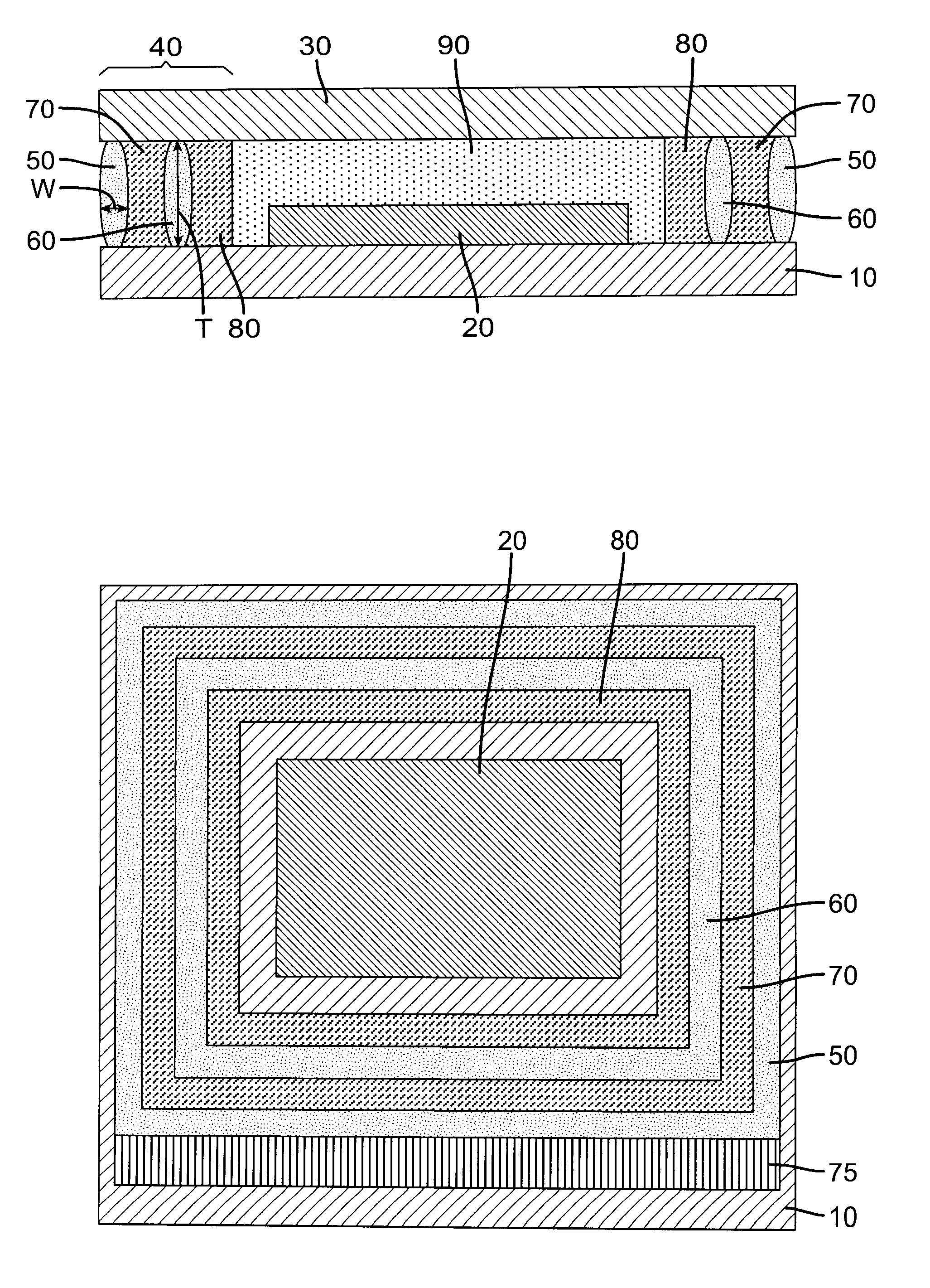
[0030] The term “OLED device” or “organic light-emitting display” is used in its art-recognized meaning of a display device having organic light-emitting diodes as pixels. A color OLED device emits light of at least one color. The term “multicolor” is employed to describe a display panel that is capable of emitting light of a different hue in different areas. In particular, it is employed to describe a display panel that is capable of displaying images of different colors. These areas are not necessarily contiguous. The term “full color” is commonly employed to describe multicolor display panels that are capable of emitting in the red, green, and blue regions of the visible spectrum and displaying images in any combination of hues. The red, green, and blue colors constitute the three primary colors from which all other colors can be generated by appropriate mixing. However, the use of additional colors to extend the color gamut of the device is possible. The term “bottom-emitting” r...


PUM


Abstract

A method of encapsulating an OLED device, comprising: providing a substrate; forming an OLED device over the substrate, and a cover over the OLED device; and providing a desiccant sealing arrangement between the cover and the substrate, with the desiccant sealing arrangement provided by forming a perimeter seal and a spaced interior seal; a first desiccant material placed between the perimeter seal and the spaced interior seal; and a second desiccant material placed interior of the spaced interior seal.

Description

FIELD OF THE INVENTION [0001] The present invention relates to protecting OLED devices from moisture. BACKGROUND OF THE INVENTION [0002] An organic light-emitting diode device, also called an OLED device, commonly includes a substrate, an anode, a hole-transporting layer made of an organic compound, an organic luminescent layer with suitable dopants, an organic electron-transporting layer, and a cathode. OLED devices are attractive because of their low driving voltage, high luminance, wide-angle viewing, and capability for full-color flat emission displays. Tang et al. described this multilayer OLED device in their U.S. Pat. Nos. 4,769,292 and 4,885,211. [0003] A common problem with OLED displays is sensitivity to water. Typical electronic devices require humidity levels in a range of about 2500 to below 5000 parts per million (ppm) to prevent premature degradation of device performance within a specified operating or storage life of the device. Control of the environment to this ra...

Claims


Application Information

Patent Timeline
IPC IPC(8): H01L21/00
CPCH01L51/5246H01L51/5253H01L51/5259H10K50/8426H10K50/846H10K50/844
Inventor BOROSON, MICHAEL L.
Owner EASTMAN KODAK CO
Why Eureka
Try Eureka