Substrate polishing apparatus

a polishing apparatus and substrate technology, applied in the direction of flexible wheel, manufacturing tools, lapping machines, etc., can solve the problems of difficult replacement operation and difficulty for the operator to reach the expendable components, and achieve the effect of maintaining the measuring capability of the substrate measuring device, reducing the influence of the polishing abrasive on the film measurement, and reducing the influence of the measurement fluid on the polishing capability

Inactive Publication Date: 2007-07-26
EBARA CORP
View PDF13 Cites 24 Cited by
  • Summary
  • Abstract
  • Description
  • Claims
  • Application Information

AI Technical Summary

Benefits of technology

[0013] The present invention has been made in view of the above drawbacks. It is an object of the present invention to provide a substrate polishing apparatus which can reduce the influence that a polishing abrasive has on film measurement, and allows an expendable component to be replaced easily, and can reduce the influence that a measurement fluid has on the polishing capability while maintaining the measuring capability of a substrate measuring device.

Problems solved by technology

However, it is difficult for the operator to reach the expendable components, and hence the replacing operation is not easy to accomplish.

Method used


Image

  • Substrate polishing apparatus
  • Substrate polishing apparatus
  • Substrate polishing apparatus

Examples


first embodiment

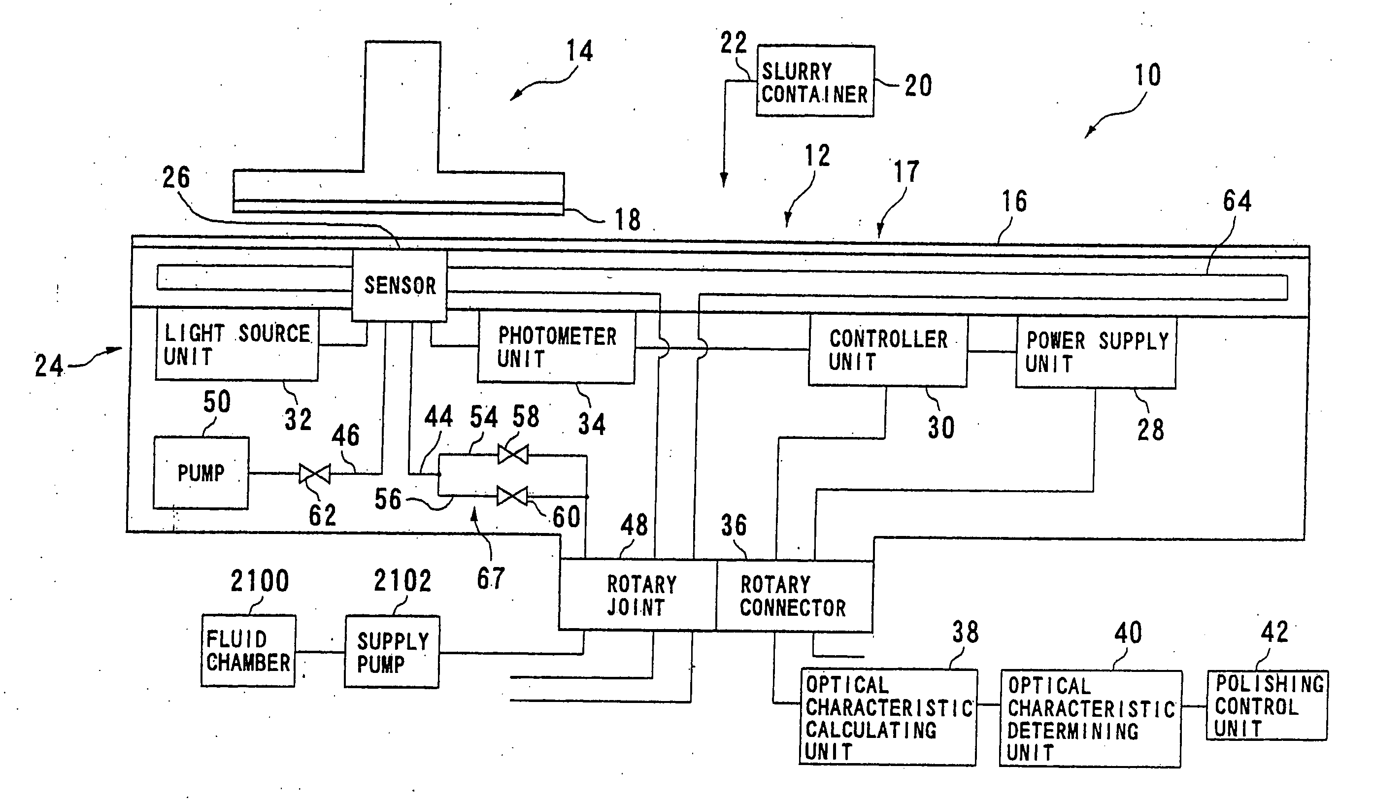
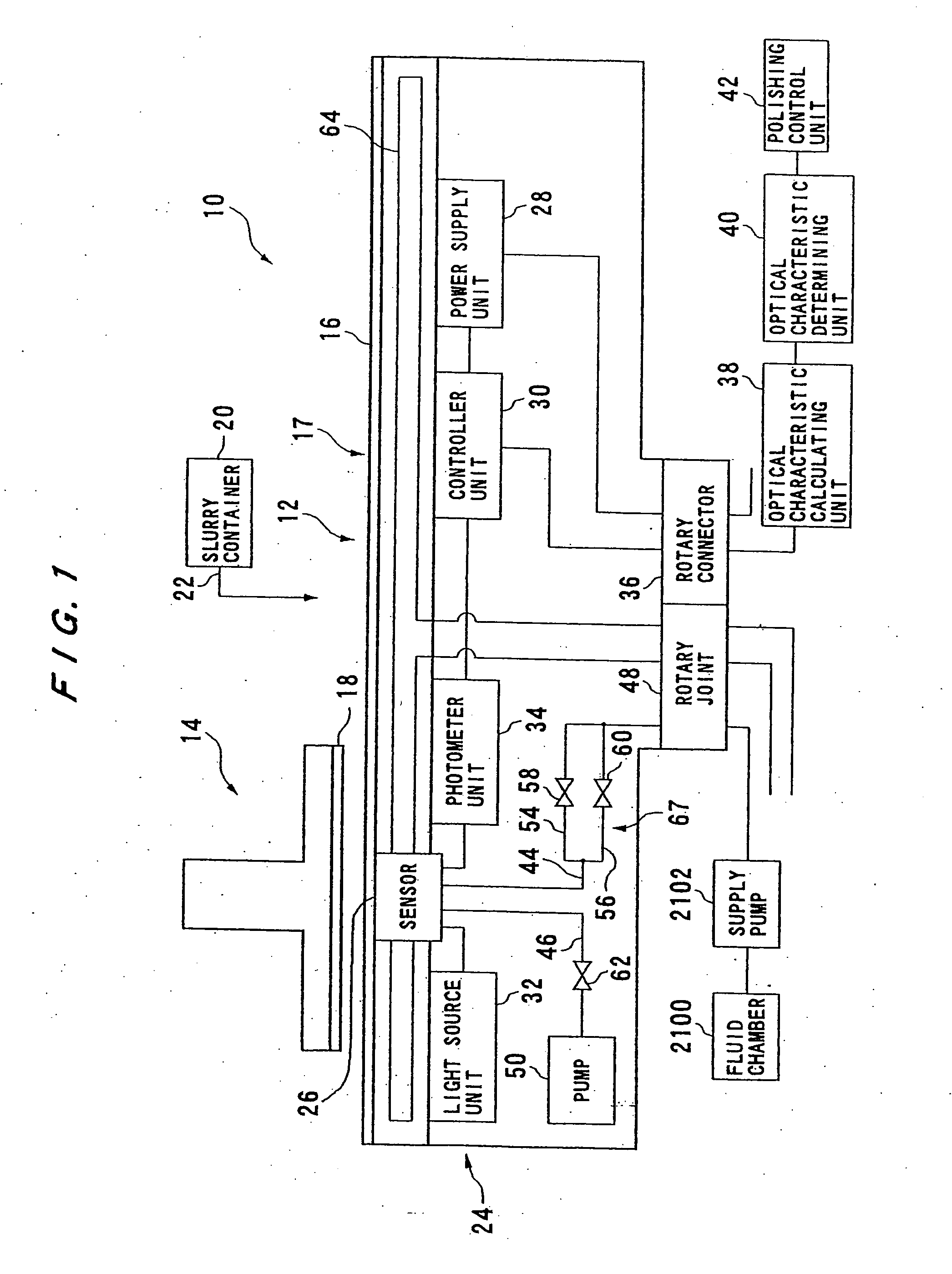
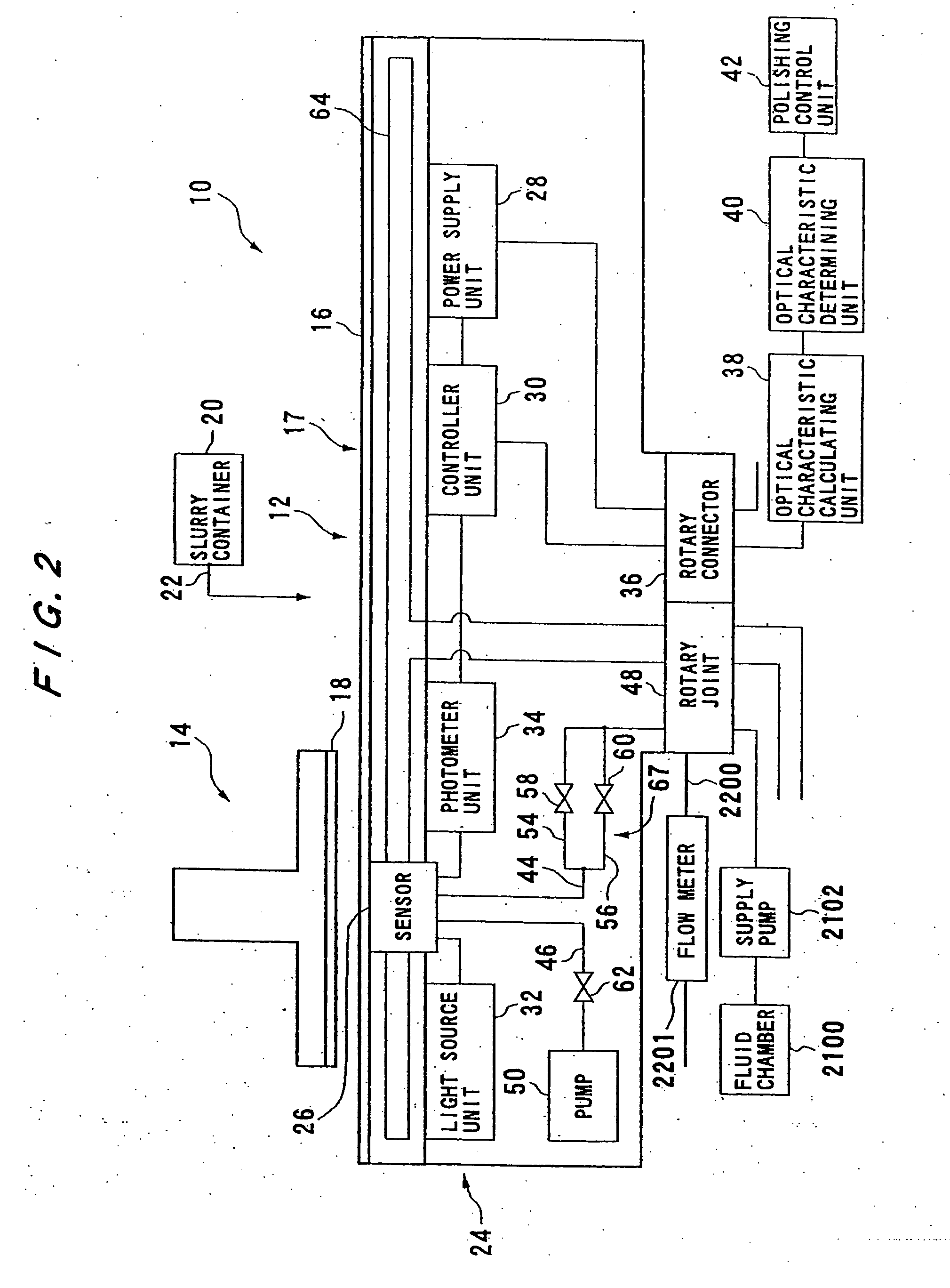
[0175]FIG. 1 shows a substrate polishing apparatus according to the present invention. FIG. 2 shows another example of an entire structure of the substrate polishing apparatus shown in FIG. 1. The substrate polishing apparatus 10 is a so-called chemical mechanical polishing (CMP) apparatus, and has a rotatable table (polishing table) 12 and a top ring 14. A polishing pad 16 is attached to the rotatable table 12. As the polishing pad 16, a fixed abrasive type polishing pad which is formed by fixing polishing abrasive particles by a binder agent such as epoxy may be used in addition to a polishing cloth made of polyurethane foam, a nonwoven fabric type polishing cloth, and a suede type polishing cloth. The top ring 14 supports a substrate 18 on a lower surface thereof and is rotated together with the substrate 18. The top ring 14 presses the substrate 18 against the polishing pad 16 at a location away from a center of the rotatable table 12. Slurry (polishing abrasive) for polishing i...

fourth embodiment

[0246] As described above, with the substrate polishing apparatus 10 since the outlet portion can be moved by the piezoelectric element 174 serving as an outlet portion moving means, the outlet portion can be moved into the through hole 84 after the polishing pad 16 is attached to the rotatable table 12.

[0247] The outlet portion can be moved and accommodated in the rotatable table 12 before the polishing pad 16 is removed. Therefore, the polishing pad 16 can be easily replaced without causing damage to the outlet portion. The outlet portion projects from the rotatable table 12 to be positioned closely to the substrate 18. Therefore, the flow velocity of the fluid supplied from the supply passage 44 is increased at the outlet portion, and the fluid is vigorously ejected from the gap between the substrate 18 and the outlet portion toward the outside of the supply passage 44, thus forming a flow along the substrate 18. The flow of the fluid can effectively remove the polishing abrasiv...

fifth embodiment

[0257]FIG. 14 is a view showing a modification of the substrate polishing apparatus according to the This modification is different in that a ball screw 186 is employed instead of the piezoelectric element 174 for moving the light-emitting optical fiber 80 and the light-receiving optical fiber 82. The ball screw 186 is mounted on the light-emitting optical fiber 80 and the light-receiving optical fiber 82. The ball screw 186 is connected to a ball screw actuating circuit 188. The calculating unit 180 for calculating an amount of received light detected by the photometer unit 34 is connected to the controller unit 30. The controller unit 30 sends a command signal to the ball screw actuating circuit 188 based on the amount of the received light calculated by the calculating unit 180 so as to control the movement of the light-emitting optical fiber 80 and the light-receiving optical fiber 82.

[0258] According to this modification, as with the above embodiment, the control unit 30 contr...


PUM

PropertyMeasurementUnit
distance d3aaaaaaaaaa

Abstract

A substrate polishing apparatus is used to polish a surface of a substrate such as a semiconductor wafer to a flat mirror finish. The substrate polishing apparatus has a polishing table and a polishing pad mounted on the polishing table for polishing a semiconductor substrate. The polishing pad has a through hole formed therein. The substrate polishing apparatus also has a light emission and reception device for emitting measurement light through the through hole formed in the polishing pad to the semiconductor substrate and receiving reflected light from the semiconductor substrate so as to measure a film on the semiconductor substrate. The light emission and reception device is disposed in the polishing table. The substrate polishing apparatus includes a supply passage for supplying a fluid to a path of the measurement light. The supply passage has an outlet portion detachably mounted on the polishing table. The substrate polishing apparatus also includes a protection cover mounted on the polishing table and fitted into the through hole when the polishing pad is attached to the polishing table.

Description

[0001] This application is a divisional application of U.S. application Ser. No. 11 / 274,112, filed Nov. 16, 2005, which is a continuation-in-part of U.S. application Ser. No. 10 / 617,794 filed Jul. 14, 2003 and international application No. PCT / JP2004 / 006768 filed May 13, 2004.BACKGROUND OF THE INVENTION [0002] 1. Field of the Invention [0003] The present invention relates to a substrate polishing apparatus, and more particularly to a substrate polishing apparatus capable of improving measurement accuracy of a substrate measuring device which is incorporated in the substrate polishing apparatus. [0004] 2. Description of the Related Art [0005] In a semiconductor fabrication process, a substrate polishing apparatus is used to polish a surface of a substrate such as a semiconductor wafer to a flat and mirror surface. The substrate polishing apparatus has a rotatable table (polishing table), and a substrate is pressed against a polishing surface on the rotatable table. Then, while a poli...

Claims


Application Information

Patent Timeline
Patent Type & Authority Applications(United States)
IPC IPC(8): B24B49/00B24B37/013B24B37/04B24B37/20B24B49/12B24D13/14H01L21/306
CPCB24B37/013H01L21/30625B24B49/12B24B37/205B24B37/00B24B37/26H01L21/304
Inventor HIROKAWA, KAZUTONAKAI, SHUNSUKEOHTA, SHINROUWADA, YUTAKAKOBAYASHI, YOICHI
Owner EBARA CORP
Why Eureka
Try Eureka