Second-order intermodulation distortion compensating circuit

Inactive Publication Date: 2007-07-26
SAMSUNG ELECTRONICS CO LTD
View PDF5 Cites 56 Cited by
  • Summary
  • Abstract
  • Description
  • Claims
  • Application Information

AI Technical Summary

Benefits of technology

[0014] Exemplary embodiments of the present invention provide a second-order intermodulatio

Problems solved by technology

In spite of these advantages, however, the direct conversion receiver still has disadvantages to be overcome, for example, mismatches between mixers cause poor performance of the direct conversion receiver.
It is not difficult to implement the mixer load to be well matched when the RF signal is

Method used


Image

  • Second-order intermodulation distortion compensating circuit
  • Second-order intermodulation distortion compensating circuit
  • Second-order intermodulation distortion compensating circuit

Examples


Embodiment Construction

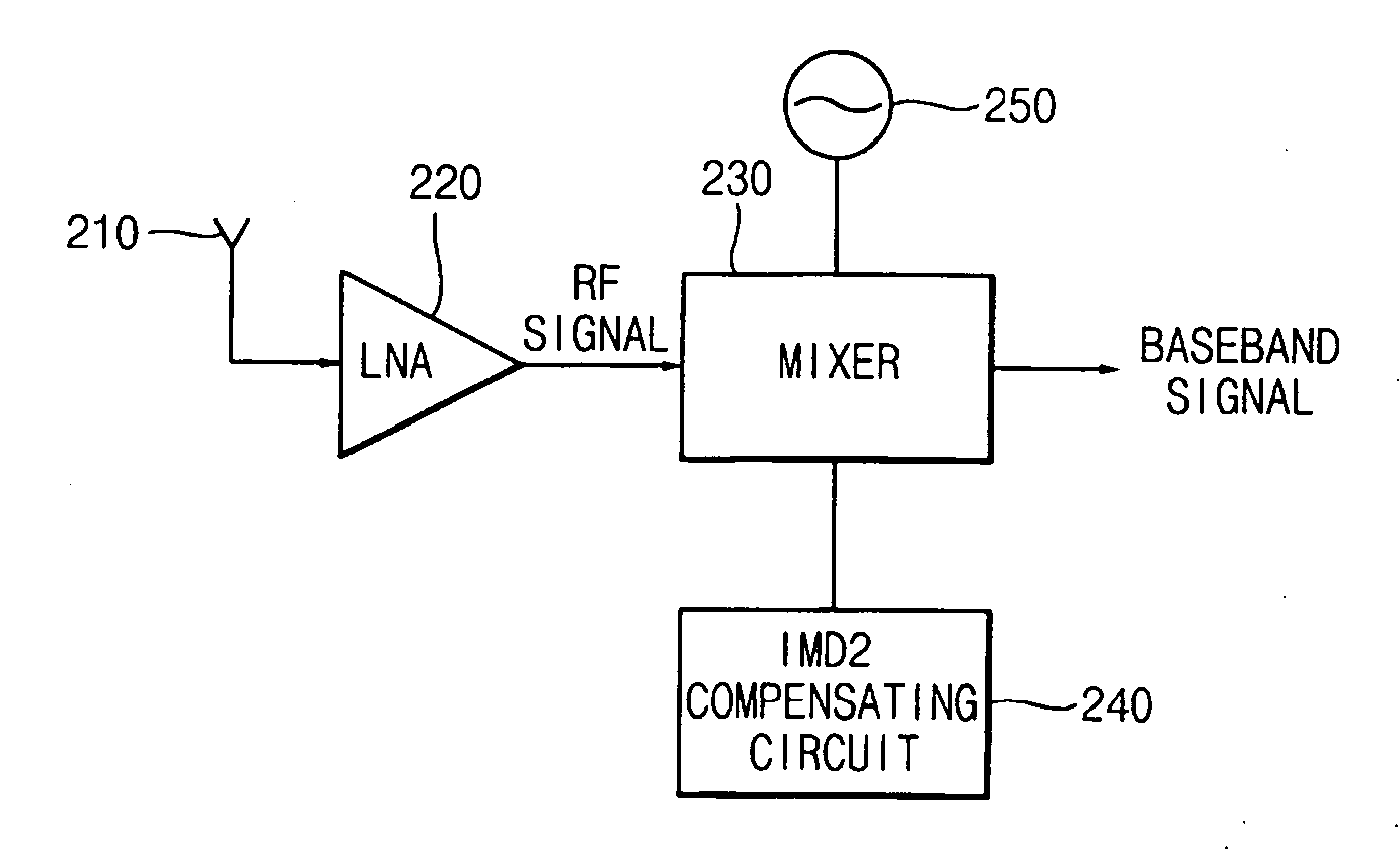
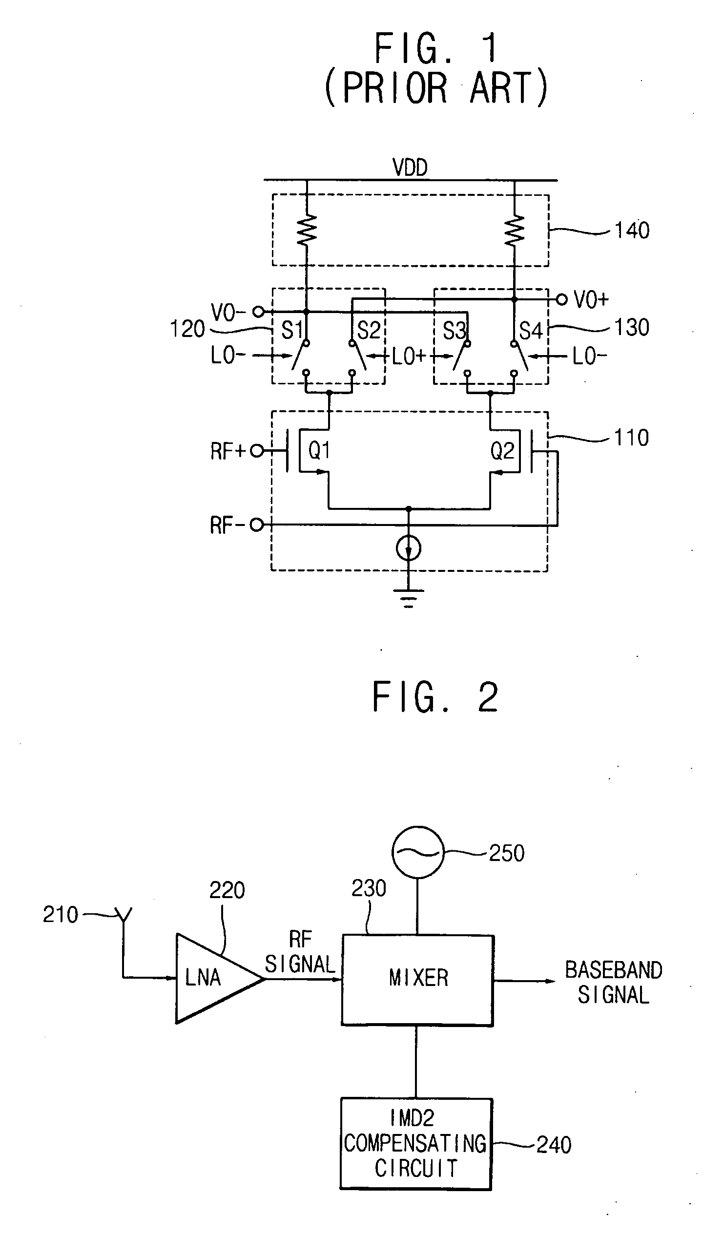
[0044]FIG. 2 is a block diagram illustrating a direct conversion receiver according to an exemplary embodiment of the present invention.

[0045] A direct conversion receiver includes a receiving circuit 210 for receiving a radiofrequency (RF) signal, a low noise amplifier (LNA) 220 for amplifying the received RF signal, a mixer 230, a second-order intermodulation distortion (IMD2) compensating circuit 240 for calibrating output signals from the mixer 230, and a local oscillator 250.

[0046] The receiving circuit 210 receives an RF signal among RF signals transmitted through a media. To do this, the receiving circuit 210 may include an antenna, a band pass filter, and so on.

[0047] The LNA 220 amplifies the received RF signal enough to be processed at the following stage, and the amplified RF signal is provided to the mixer 230.

[0048] The mixer 230 performs down-conversion with respect to the amplified RF signal directly to the base band. For the performance of the mixer 230, the loca...


PUM


Abstract

A second-order intermodulation distortion (IMD2) compensating circuit that detects a variation of DC level of a voltage pair of a mixer load and adjusts the variation of the DC level of the voltage pair. The second-order intermodulation distortion compensating circuit also calibrates a mismatch of a mixer as well as a mismatch of the mixer load.

Description

CROSS-REFERENCE TO RELATED APPLICATION [0001] This application claims the benefit under 35 U.S.C. § 119 of Korean Patent Application No. 2005-0099094 filed on Oct. 20, 2005, the contents of which are herein incorporated by reference in its entiretyBACKGROUND OF THE INVENTION [0002] 1. Technical Field [0003] The present disclosure relates to wireless telecommunications. More particularly, the present disclosure relates to wireless telecommunications using a direct conversion scheme. [0004] 2. Discussion of the Related Art [0005] A wireless telecommunications system enables communication between a transmitter and a receiver, which are apart from each other, by transmitting a baseband signal carried on by a high-frequency carrier signal. [0006] To retrieve a baseband signal, a superheterodyne receiver downconverts a radio frequency (RF) signal to an intermediate frequency (IF) signal and then downconverts the IF signal to the baseband signal. The superheterodyne receiver exploits the I...

Claims


Application Information

Patent Timeline
IPC IPC(8): H04B1/10
CPCH04B1/30H04B1/109H04B1/10
Inventor KIM, YOUNG-JINKIM, WOO-NYUN
Owner SAMSUNG ELECTRONICS CO LTD
Why Eureka
Try Eureka