Data processing apparatus

a data processing and apparatus technology, applied in the direction of electric digital data processing, instruments, etc., can solve the problems of affecting system performance, bus performance is a great factor affecting system performance, and it is difficult to correctly control the car, etc., and achieve the effect of high data transfer efficiency

Inactive Publication Date: 2007-07-26
FUJITSU LTD
View PDF9 Cites 52 Cited by
  • Summary
  • Abstract
  • Description
  • Claims
  • Application Information

AI Technical Summary

Benefits of technology

[0042] The present invention is made in view of the above problems, and the object of the present invention is to provide a data processing apparatus which exhibits high efficiency in data transfer performed in response to a read-transfer request.

Problems solved by technology

However, when the image processing is delayed, it becomes impossible to correctly control the car.
In addition, in the image processing, in which real-time processing of a great amount of data is required, the bus performance is a great factor which affects the system performance.
Therefore, when the data-transfer performance of a bus is low, the processing engine cores are required to wait for data, and cannot exhibit their full processing capabilities.
Therefore, in image processing systems, the efficiency in the DMA transfer affects the bus performance, and the bus performance affects the performance of the entire system.
However, when a fault occurs during the burst transfer, information on the fault is not sent until the burst transfer is completed.
However, when DMA transfer is performed through a CPU bus, the CPU bus is uselessly occupied in a substantial number of cycles during execution of a request to read and transfer data (read-transfer request), so that the efficiency in the DMA transfer decreases.
In many cases, when a right of use of a bus is obtained, the amount of data which can be transferred before the right of use is released (i.e., the maximum transferable data size) is limited by a bus specification.
This is because if a bus is occupied for a long time by a data transfer performed in response to a request from one of a plurality of sources of data-transfer requests (e.g., a plurality of devices which output a request to transfer data), data transfers in response to requests from the other sources of data-transfer requests are impeded, so that processing to be performed by the other sources of data-transfer requests is delayed, and the real-time performance of the processing performed by the other sources of data-transfer requests is likely to be impaired.
Therefore, the division of the data to be transferred lowers the efficiency in the DMA transfer.
Thus, the efficiency in the DMA transfer is seriously lowered.
Therefore, in practice, the multiplicity of the requests is limited.
Further, in some cases, the specifications of installed processor cores do not allow use of a multilayer bus structure as in the AMBA AXI system, so that the efficiency in the DMA transfer cannot be increased.
However, after the line width reaches 100 nm, the operational frequency is also approaching its limit.
There is a problem which relates to improvement in the data transfer efficiency in the image processing and is specific to the image processing.

Method used


Image

  • Data processing apparatus
  • Data processing apparatus
  • Data processing apparatus

Examples


first embodiment

[0076] In the first embodiment, an example of an LSI (Large Scale Integrated Circuit) which performs processing of a great amount of data in real time is presented.

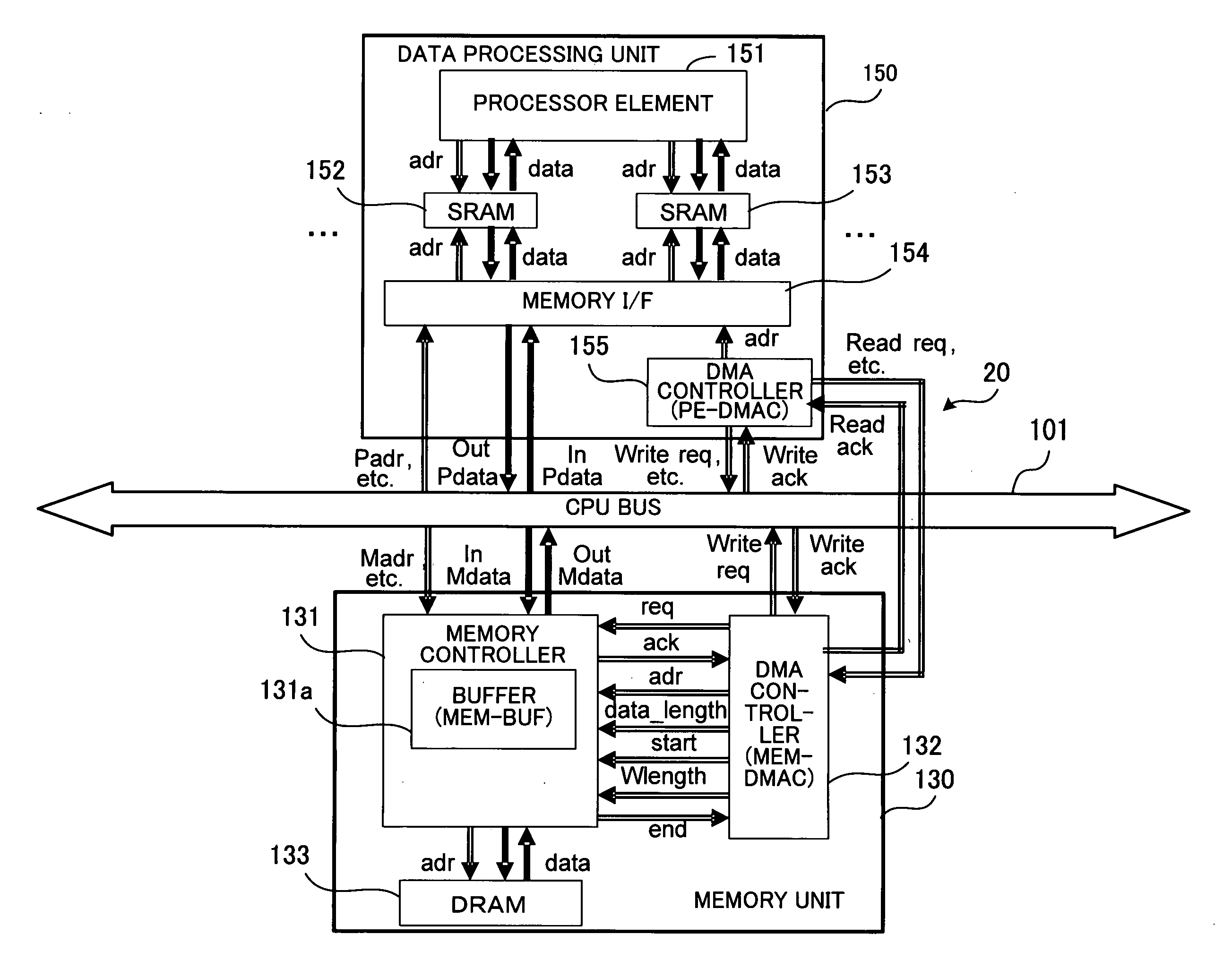
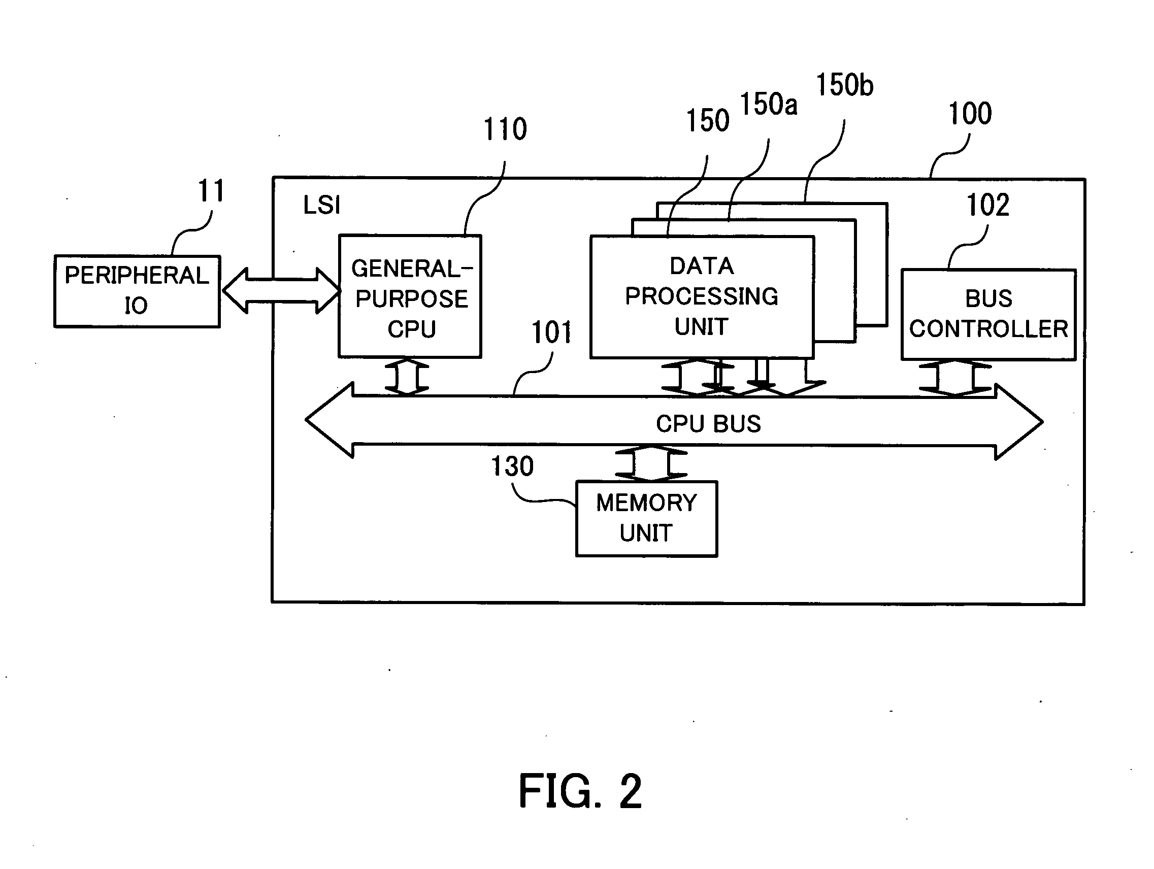
[0077]FIG. 2 is a diagram illustrating an example of a construction of an LSI as the first embodiment of the present invention. The LSI 100 comprises a CPU bus 101 controlled by a bus controller 102. In addition, a general-purpose CPU 110, a memory unit 130, and a plurality of data processing units 150, 150a, 150b, . . . are connected to the CPU bus 101.

[0078] The general-purpose CPU 110 performs various data processing. In addition, a peripheral IO (input / output) interface 11 is connected to the general-purpose CPU 110, so that the general-purpose CPU 110 can receive and output data through the peripheral IO interface 11.

[0079] The memory unit 130 contains a DRAM. The memory unit 130 writes and reads data in and from the DRAM, and performs data transfer through the CPU bus 101.

[0080] The data processing units 150, 15...

second embodiment

[0113] Next, the second embodiment of the present invention is explained below. In the second embodiment, the present invention is applied to an LSI (Large Scale Integrated Circuit) for image processing. In order to handle image data, the LSI according to the second embodiment has a function of storing data read out from a two-dimensional rectangular area in a frame memory, at consecutive addresses.

[0114]FIG. 7 is a diagram illustrating an example of a construction of the LSI for image processing according to the second embodiment of the present invention. The LSI 200 comprises a CPU bus 201 controlled by a bus controller 202. In addition, a general-purpose CPU 210, an image- input interface (I / F) 220, a memory interface (I / F) unit 230, an image-output interface (I / F) 240, and a plurality of image-processing engines 250, 250a, 250b, . . . are connected to the CPU bus 201.

[0115] The general-purpose CPU 210 performs various data processing. In addition, a peripheral IO (input / output...


PUM


Abstract

A data processing apparatus in which DMA transfer is performed. When a processor in a data processing unit outputs a first request to read data managed by a data management unit, a receiver-side DMA controller outputs a second request for DMA transfer, from the data processing unit to the data management unit through a dedicated line. Next, a memory controller in the data management unit reads out from the memory the data designated by the second request, and stores the data in a buffer. Then, a transmitter-side DMA controller acquires a right of use of a bus, and the memory controller transfers the data stored in the buffer, through the bus by DMA, and writes the data in a data storage area in the data processing unit.

Description

CROSS-REFERENCE TO RELATED APPLICATIONS [0001] This application is based upon and claims the benefits of priority from the prior Japanese Patent Application No. 2005-380609, filed on Dec. 29, 2005, in Japan, and the contents of which are incorporated herein by reference. BACKGROUND OF THE INVENTION [0002] 1. Field of the Invention [0003] The present invention relates to a data processing apparatus which performs DMA (Direct Memory Access) transfer, and in particular, to a data processing apparatus which is required to perform real-time processing. [0004] 2. Description of the Related Art [0005] Currently, the information processing technology is used in various fields. Among others, in some technical fields including image processing, processing of a great amount of data is required. In particular, in some particular applications, processing of a great amount of data is required to be performed in real time. [0006] For example, in a known technique, images taken by a camera mounted ...

Claims


Application Information

Patent Timeline
Patent Type & Authority Applications(United States)
IPC IPC(8): G06F13/28
CPCG06F13/28
Inventor TSURUTA, TORU
Owner FUJITSU LTD
Why Eureka
Try Eureka