Rotary flash ADC

a technology of rotary oscillator and analogtodigital converter, which is applied in the direction of pulse automatic control, electric analogue stores, instruments, etc., can solve the problems of difficult calibration, large amount of power and area of flash converters, etc., and achieve the effect of high conversion accuracy

Active Publication Date: 2007-08-02
ANALOG DEVICES INC
View PDF37 Cites 16 Cited by
  • Summary
  • Abstract
  • Description
  • Claims
  • Application Information

AI Technical Summary

Benefits of technology

[0009] One advantage of the present invention is that conversion happens very quickly as the conversion time is the sum of the sample time and the time-to-digital conversion time. If the sample time is 500 pS and the time conversion time is equal to the sample time, then a full analog-to-digital conversion would occur in about 1 nS.
[0010] Another advantage is that there is no need for a calibration cycle that makes the converter unavailable. In the present invention, calibration occurs while the converter is operational and does not interfere with normal operation.
[0011] Yet another advantage is that the conversion is highly accurate, the accuracy limit being set by the number of phases of the multiphase clock.

Problems solved by technology

Flash converters tend to require a large amount of both power and area and are difficult to calibrate.

Method used


Image

  • Rotary flash ADC
  • Rotary flash ADC
  • Rotary flash ADC

Examples


Embodiment Construction

Overall Operating Principle

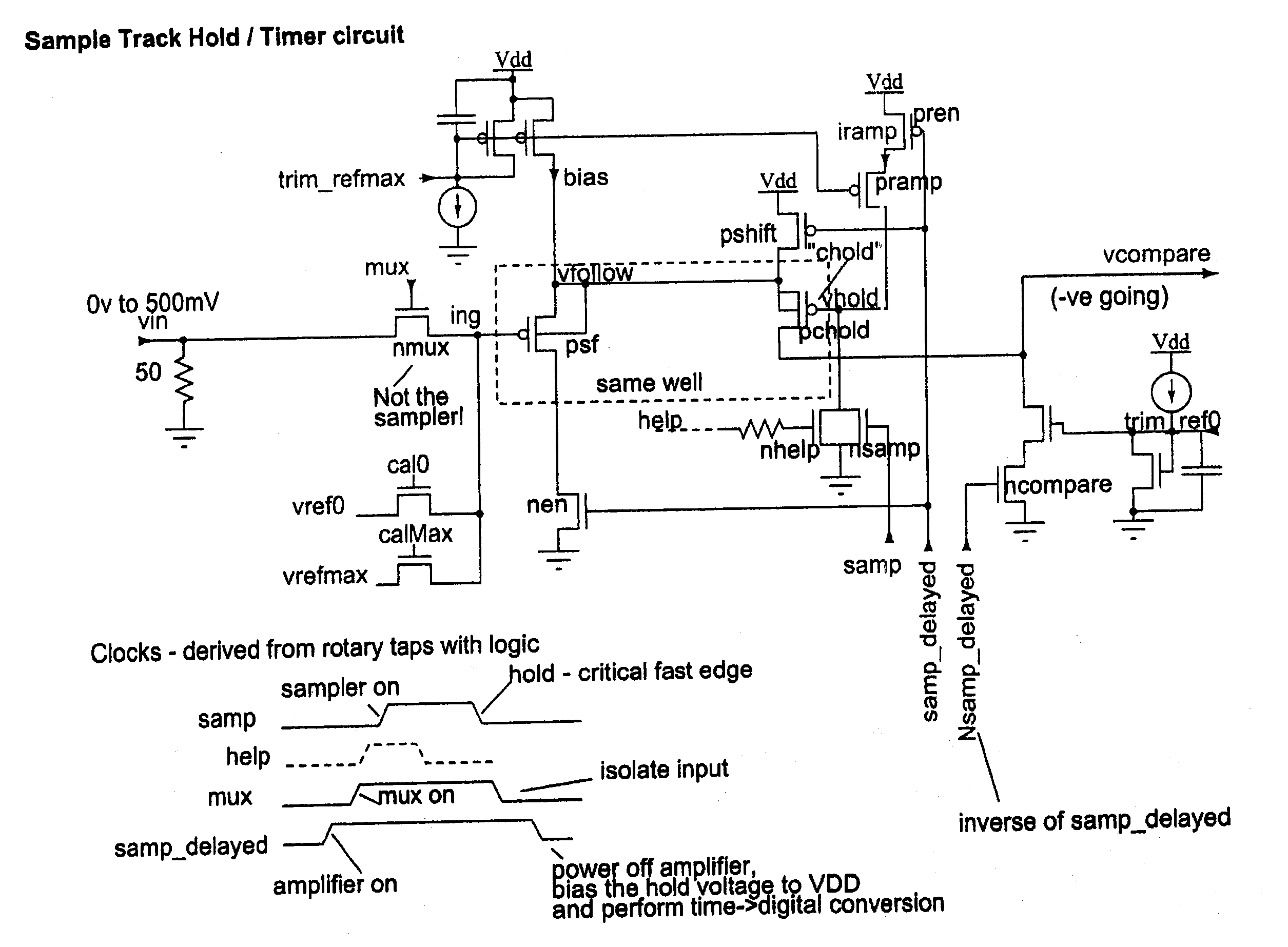
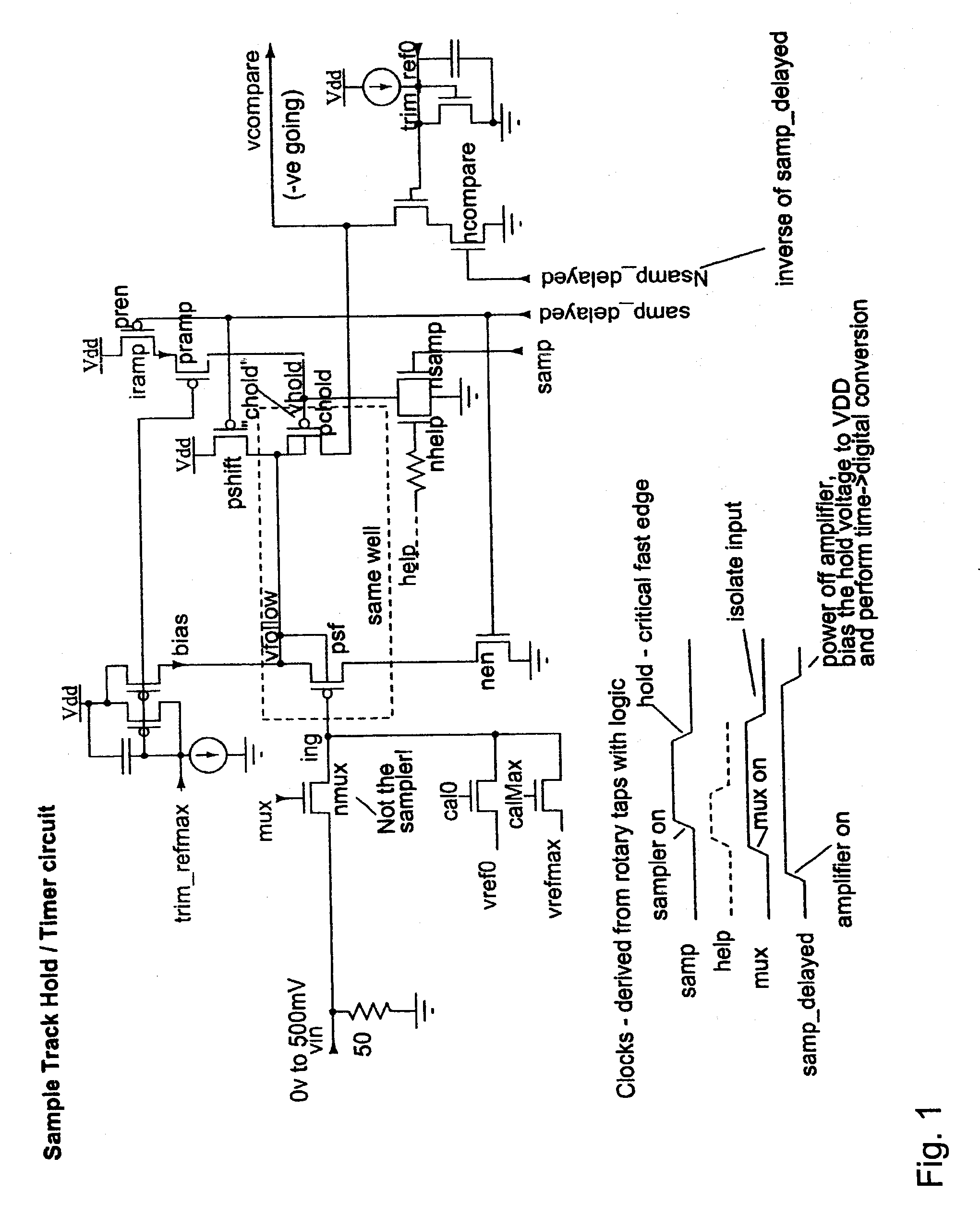
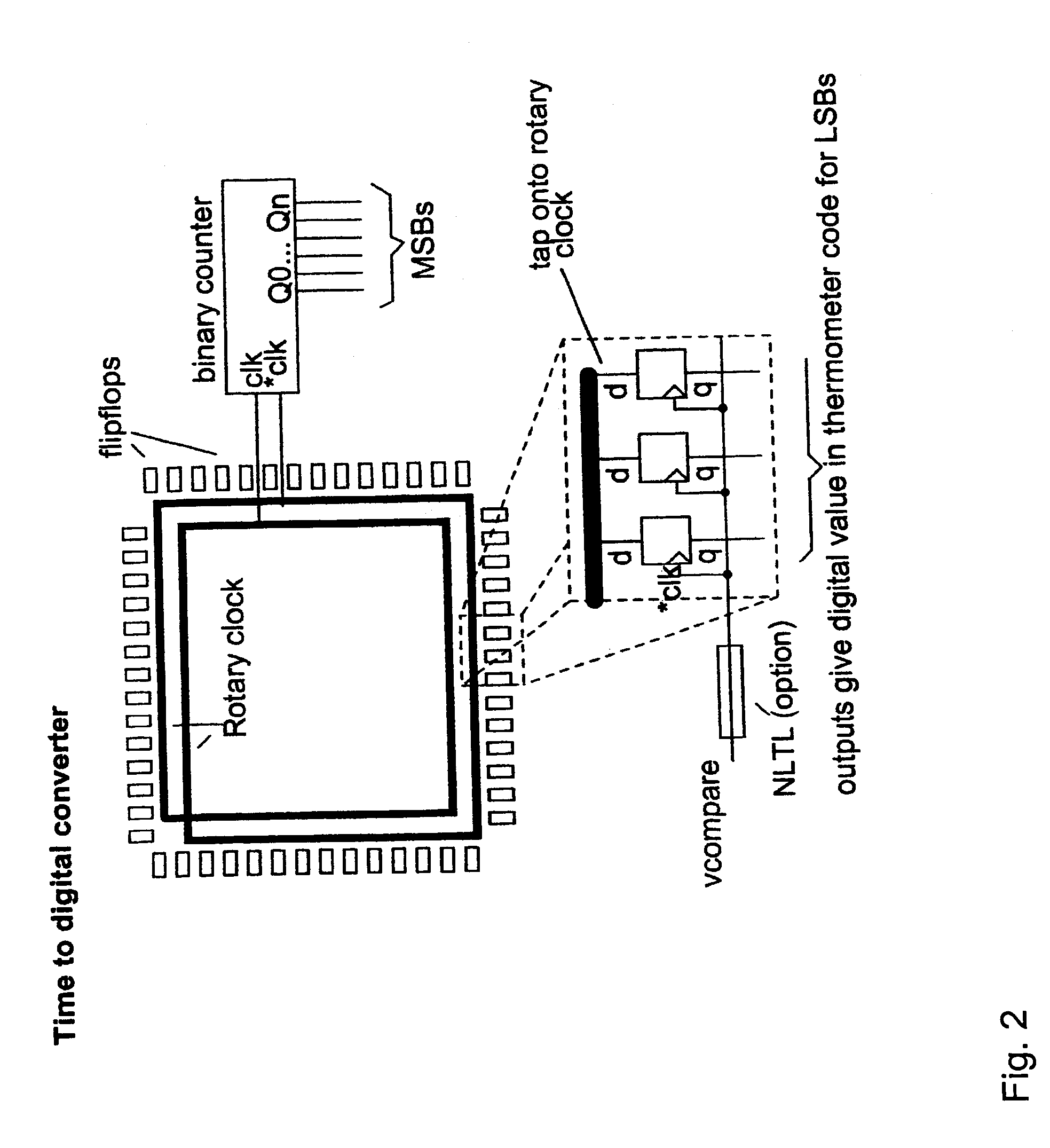
[0018] The basic operating principle is that of single-slope ADC conversion using a track-and-hold sampler on the input and a multiphase time-to-digital conversion on the output. Fragmentation and interleaving of the ADC construction allows for transparent self-calibration while conversions are in progress.

[0019]FIG. 1 is the simplified diagram of the new sampler and converter technique constructed on a low cost digital CMOS process where only the PFETs have independent wells (NFET circuits could be used on a true twin-tub process). At the front-end is a voltage buffer and a track and hold circuit. An input multiplexer (not a sampler) is provided to allow auto-calibration, etc. The track and hold circuit shown is a PFET source follower and the sampler capacitor is chosen to be a PFET enhancement mode capacitance formed in transistor PHOLD (which also doubles as the comparator transistor). Of course, a true capacitor could be used.

[0020] After the sampl...


PUM


Abstract

A system and method for converting an analog signal to a digital signal is disclosed. The system includes a multiphase oscillator preferable a rotary oscillator, a sample and hold circuit, an integrator and a time-to-digital converter. The multiphase oscillator has a plurality of phases that are used in the time-to-digital converter to measure the time of a pulse created by the integrator. The edges of the pulse may optionally be sharpened by passing the pulse through a non-linear transmission line to improve the accuracy of the measurement process. To cut down on noise a tuned power network provides power to the switching devices of the rotary oscillator. Calibration is performed by fragmenting the sample and hold circuit and integrator and performing a closed loop calibration cycle on one of the fragments while the other fragments are joined together for the normal operation of the sample and hold and integrator circuits.

Description

CROSS-REFERENCE TO RELATED APPLICATIONS [0001] This application is a continuation of and incorporated by reference U.S. patent application Ser. No. 11 / 191,231 filed Jul. 26, 2005, titled “ROTARY FLASH ADC,” which claims priority to and incorporates by reference Great Britain application GB 0416803, filed Jul. 27, 2004. [0002] This application is related to U.S. application, titled “DOUBLE FEEDBACK RTWO DRIVEN SAMPLER CIRCUITS”, Ser. No. 11 / 051,989, filed Feb. 3, 2005, and is incorporated by reference into the present application. [0003] The publication, Rotary Traveling-Wave Oscillator Arrays: A New Clock Technology, J. Wood, T. C. Edwards, and S. Lipa, IEEE Journal of Solid-State Circuits, Vol. 36, pp. 1654-1665, is incorporated by reference into the present application.FIELD OF THE INVENTION [0004] The present application relates generally to analog-to-digital converters and more particularly to an analog-to-digital converter with a rotary oscillator. DESCRIPTION OF THE RELATED AR...

Claims


Application Information

Patent Timeline
Patent Type & Authority Applications(United States)
IPC IPC(8): H03M1/12G11C27/02
CPCG11C27/026G04F10/005G11C27/024H03M1/1004H03M1/145H03M1/502H03M1/504H03M1/54
Inventor WOOD, JOHN
Owner ANALOG DEVICES INC
Why Eureka
Try Eureka