
Fuel cell separator and production process thereof

a technology of fuel cell separator and production process, which is applied in the field of separator, can solve the problems of high durability, difficult to obtain high durability, and difficult to cover metal, and achieve the effects of reducing contact resistance and penetration resistance, reducing contact resistance, and increasing electroconductivity

Inactive Publication Date: 2007-08-02
SHOWA DENKO KK
View PDF1 Cites 16 Cited by
  • Summary
  • Abstract
  • Description
  • Claims
  • Application Information

AI Technical Summary

Benefits of technology

[0025] Another object of the present invention is to provide a fuel cell separator which has a low contact resistance and a low penetration resistance.
[0027] As a result of further study, the present inventors have also found that the contact resistance and the penetration resistance can further be reduced, by incorporating a polymer of the same type, or polymers constituting a pair of compatible (or mutually soluble) polymers, into the compositions constituting the respective layers.

Problems solved by technology

Among these materials, metals have a problem in the corrosion resistance thereof and therefore, an attempt has been made to cover the surface thereof with a noble metal or carbon.
However, even in such a case, a sufficiently high durability cannot be obtained and moreover, the cost for covering the metal is problematic.
Materials subjected to a baking treatment as in these examples exhibit high electroconductivity, but the baking takes a long time and the productivity is low, and these materials have a certain problem such that they have a poor flexural strength.
Further, when cut working is necessary, the mass productivity is low and the cost becomes higher, and therefore, these materials can be hardly popularized in future.
However, in such a case, the reduction in the amount of a resin to be contained in the molded product is limited to a certain extent, because the molding property should be retained.
Accordingly, it is impossible to obtain a sufficiently high electroconductivity.
In addition, because of the large amount of the electroconductivity-imparting material contained in the molded product, the surface of the resultant molded product inevitably has a low smoothness, and a higher hardness, so that the contact resistance of the molded product produced from of an electroconductive resin composition tends to be deteriorated, and the resultant product becomes fragile.
In addition, when the surface of the molded product is covered with the binder resin, and the contact resistance thereof is deteriorated, it is necessary to adopt a method of grinding the surface the molded product.
Further, when the production process includes a baking step of heating the molded product at a high temperature of 1000-3000° C. for a long period so as to obtain a high electroconductivity, the time required for producing the molded product becomes longer, and further the production steps become complicated, and the production costs problematically become high.
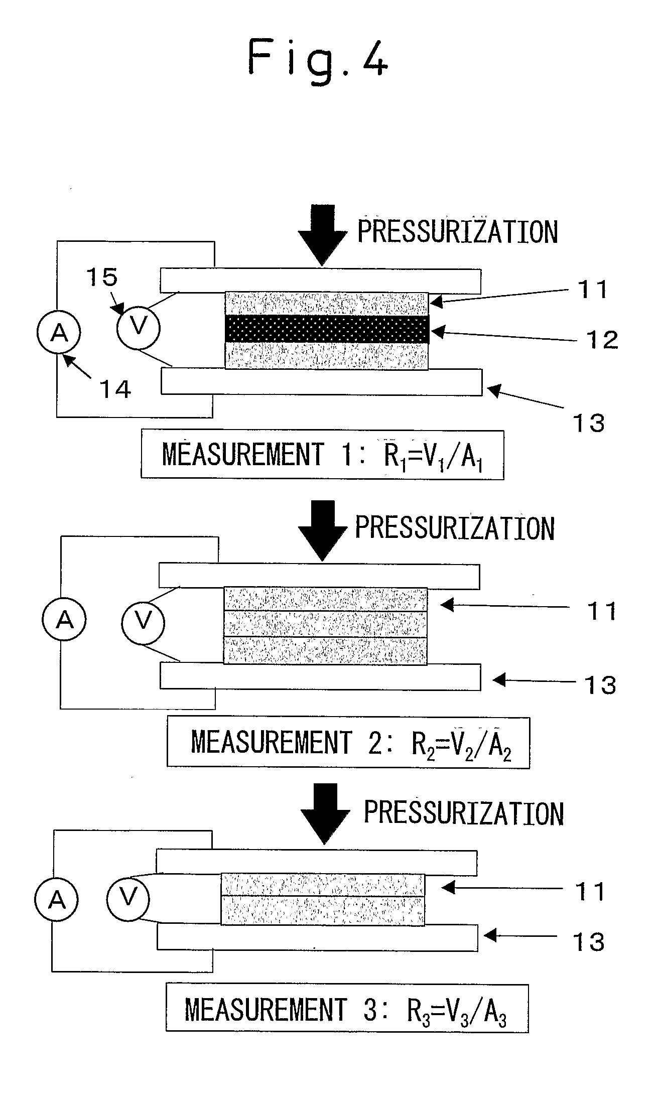
On the other hand, a multilayer-type separator has a problem such that the adhesion in a boundary portion between the different kinds of layers is mainly problematic.

Method used


Image

  • Fuel cell separator and production process thereof
  • Fuel cell separator and production process thereof
  • Fuel cell separator and production process thereof

Examples


example 1

[0168] The composition A1 and the composition B1 as shown in the above Table 2 were respectively shaped into sheets having a width of 100 mm at a temperature of 250° C., 40 rpm by using a 40φ (diameter) single-screw extruder (VS 40 / 26 Bent Type, mfd. by Tanabe Plastic Machine Co., Ltd.). Each of the resultant sheets was rolled at a temperature of 180° C. by use of rolls, so that the thickness of the composition A1 was adjusted to 0.6 mm, and the thickness of the composition B1 was adjusted to 1.8 mm. Then, these sheets were laminated in order of A1 / B1 / A1, so as to provide a laminated product having such a structure, and charged into a mold capable of providing a flat plate having a size of 100 mm×100 mm×1.5 mm, and was preheated at 240° C. for 3 min., and thereafter press-heated under a pressure of 15 MPa for 3 min., by using a 50t-compression molding machine. Then, the mold was cooled under the conditions of a temperature of 25° C., and a pressure of 15 MPa for 2 min., by using a c...

examples 2-5

[0169] The compositions A2-A5 and the composition B1 as shown in the above Table 2 were respectively shaped into sheets having a width of 100 mm at a temperature of 250° C., 40 rpm by using a 40φ (diameter) single-screw extruder (VS 40 / 26 Bent Type, mfd. by Tanabe Plastic Machine Co., Ltd.). Each of the resultant sheets was rolled at a temperature of 180° C. by use of rolls, so that the thickness of each of the compositions A2-A5 was adjusted to 0.4 mm, and the thickness of the composition B1 was adjusted to 2.2 mm. Then, these sheets were laminated in order of A2 / B1 / A2, A3 / B1 / A3, A4 / B1 / A4, order of A5 / B1 / A5, respectively, so as to provide a laminated product having each of such structures, and charged into a mold capable of providing a flat plate having a size of 100mm×100 mm×1.5 mm, and was preheated at 240° C. for 3 min., and thereafter press-heated under a pressure of 15 MPa for 3 min., by using a 50t-compression molding machine. Then, the mold was cooled under the conditions of...

example 6

[0170] The composition A6 and the composition B2 as shown in the above Table 2 were respectively shaped into sheets having a width of 100 mm at a temperature of 220° C., 40 rpm by using a 40φ (diameter) single-screw extruder (VS 40 / 26 Bent Type, mfd. by Tanabe Plastic Machine Co., Ltd.). Each of the resultant sheets was rolled at a temperature of 185° C. by use of rolls, so that the thickness of the composition A6 was adjusted to 0.4 mm, and the thickness of the composition B2 was adjusted to 2.2 mm. Then, these sheets were laminated in order of A6 / B2 / A6, so as to provide a laminated product having such a structure, and charged into a mold capable of providing a flat plate having a size of 100 mm×100 mm×1.5 mm, and was preheated at 220° C. for 3 min., and thereafter press-heated under a pressure of 15 MPa for 3 min., by using a 50t-compression molding machine. Then, the mold was cooled under the conditions of a temperature of 25° C., and a pressure of 15 MPa for 2 min., by using a c...


PUM

PropertyMeasurementUnit
Temperatureaaaaaaaaaa
Lengthaaaaaaaaaa
Fractionaaaaaaaaaa

Abstract

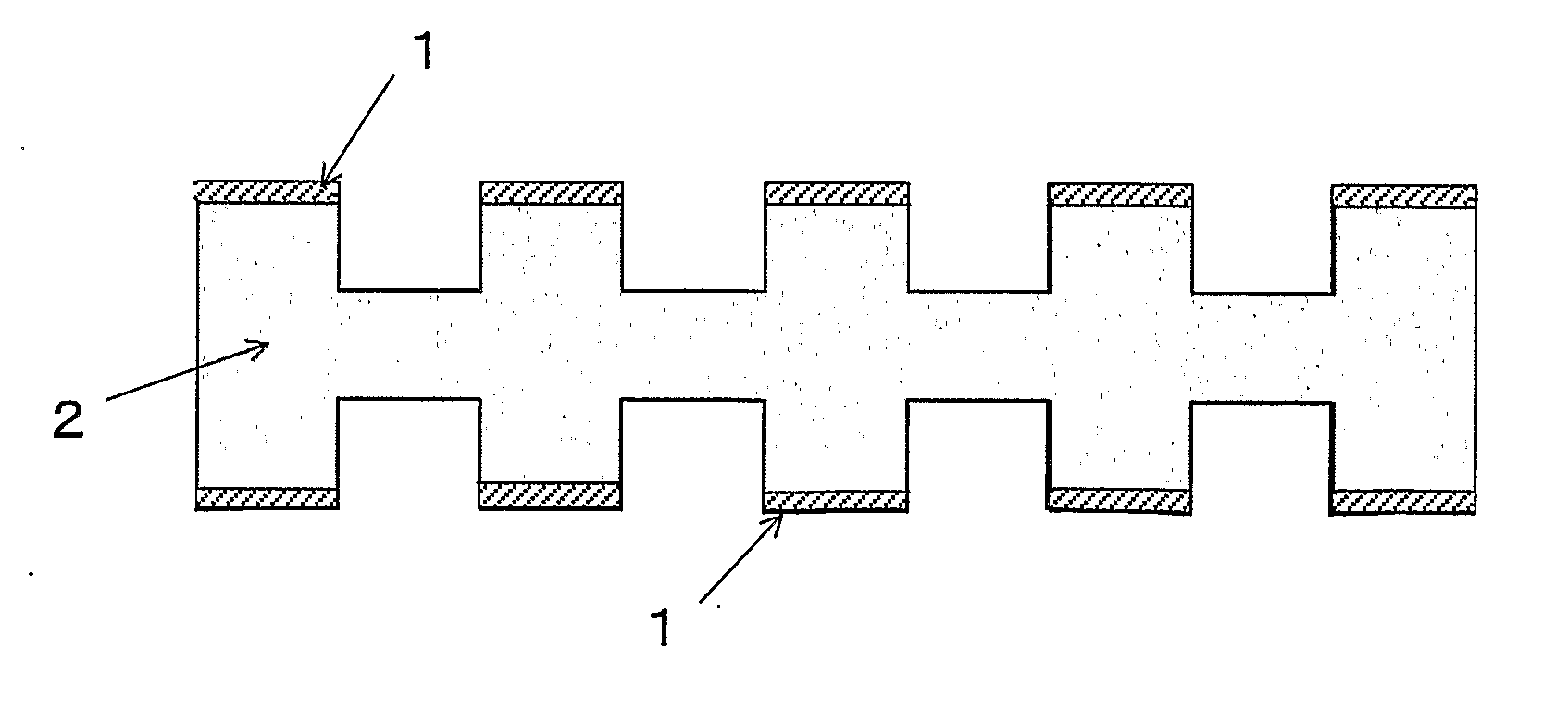
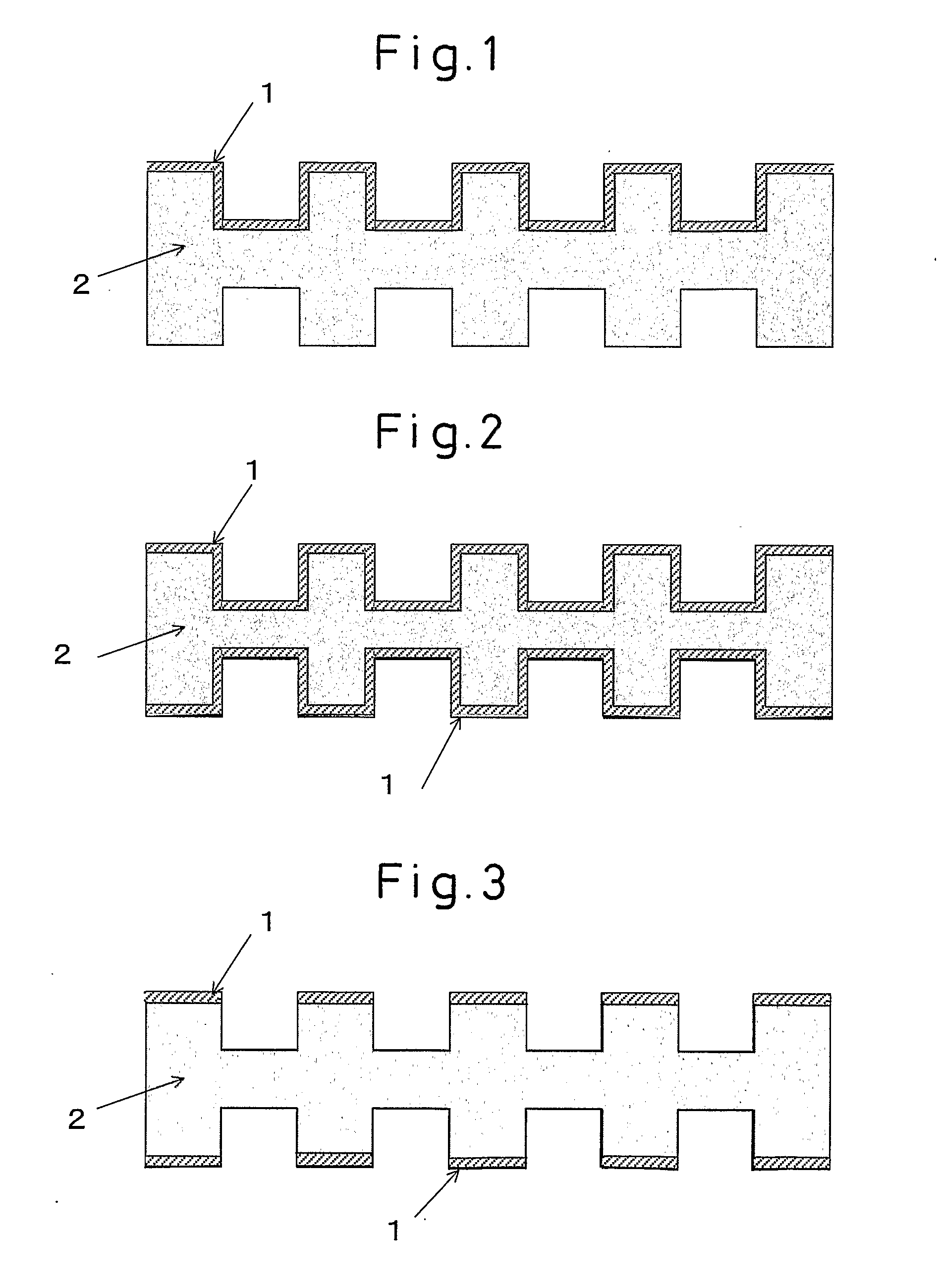
A fuel cell separator having a surface layer on one side or both sides thereof. The surface layer includes at least two layers, wherein the surface layer includes a low-elastic modulus layer (1) having a bending elastic modulus of 1.0×10<sp>1< / sp>-6.0×10<sp>3< / sp> MPa, and a bending strain of 1% or more; and a high-elastic modulus layer (2) having a bending elastic modulus exceeding 6.0×10<sp>3< / sp> MPa, as at least one layer constituting the surface layer, other than the low-elastic modulus layer (1).

Description

[0001] This application claims the priority of an application based on U.S. Provisional Application Ser. No. 60 / 534,988 (filed on Jan. 9, 2004).TECHNICAL FIELD [0002] The present invention relates to a separator having an excellent characteristic such as contact resistance and penetration resistance, and a process for producing the same. BACKGROUND ART [0003] In view of environmental problems and energy problems, fuel cells have attracted much attention as clean power-generating devices, because they generate electric power by a reverse reaction of electrolysis by using hydrogen and oxygen, and they produce no exhaust material other than water [0004] The fuel cells can be classified into several kinds, depending on the kind of the electrolyte to be used therefor. Among such fuel cells, solid polymer electrolyte-type fuel cells can work at a low temperature, and therefore they are most useful for automobile or public or civilian uses. This type of fuel cell is constructed by stacking...

Claims


Application Information

Patent Timeline
IPC IPC(8): H01M8/02B29C69/00B29C59/02
CPCH01M8/0206H01M8/0213Y02E60/50H01M8/0226H01M8/0228H01M8/0221Y02P70/50B82Y30/00H01M8/02
Inventor IINO, TADASHIIZUMI, ZENICHIRO
Owner SHOWA DENKO KK
Learn More