System and Method for Photoablation Using Multiple Focal Points with Rotating Beam Splitter

a beam splitter and multiple focal point technology, applied in the field of system and method of ophthalmic surgery, can solve the problems of unacceptable levels of adverse side effects, charring and tearing of tissue, and present procedures are still somewhat time-consuming, and achieve the effect of maximizing the efficiency of liob

Inactive Publication Date: 2007-08-02
TECHNOLAS PERFECT VISION
View PDF12 Cites 24 Cited by
  • Summary
  • Abstract
  • Description
  • Claims
  • Application Information

AI Technical Summary

Benefits of technology

[0007] In accordance with the present invention, a system and its method of operation require a capability for splitting a pulsed laser beam into a plurality of focal points. This plurality of focal points then creates a pattern that is move...

Problems solved by technology

This alteration by LIOB will typically involve the vaporization of tissue and, if uncontrolled, can include unacceptable levels of adverse side effects such as the charring and tearing of the tissue.
Although presently available laser surgical systems are capable of controlling pulse energy while rapidly pulsing a laser beam, and although they are also capable of moving the focal point relatively rapidly through the tissue to be alter...

Method used


Image

  • System and Method for Photoablation Using Multiple Focal Points with Rotating Beam Splitter
  • System and Method for Photoablation Using Multiple Focal Points with Rotating Beam Splitter

Examples


Embodiment Construction

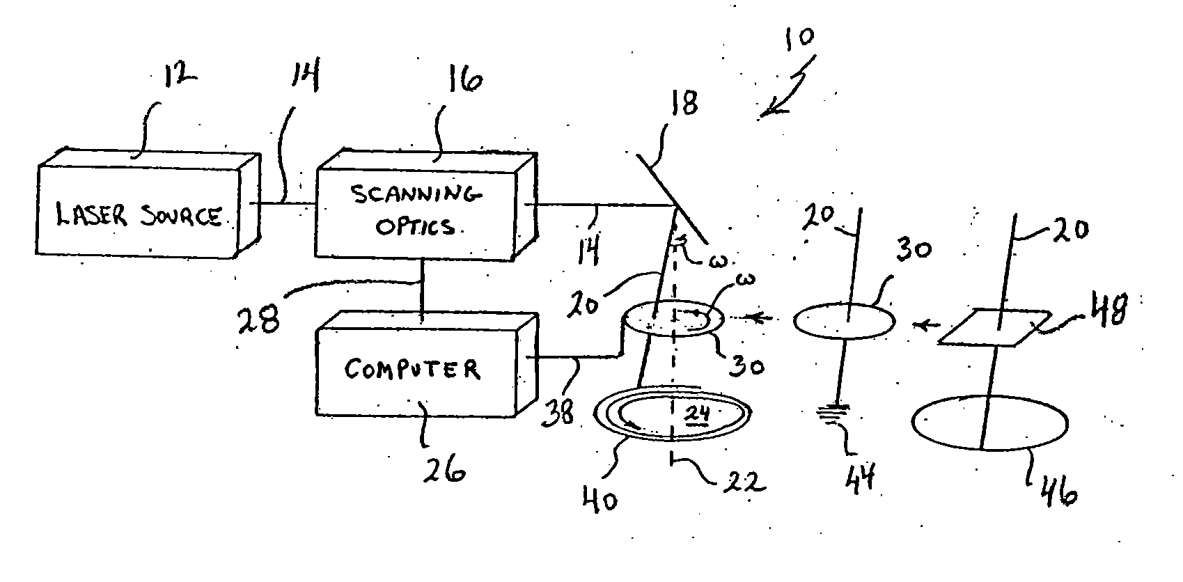
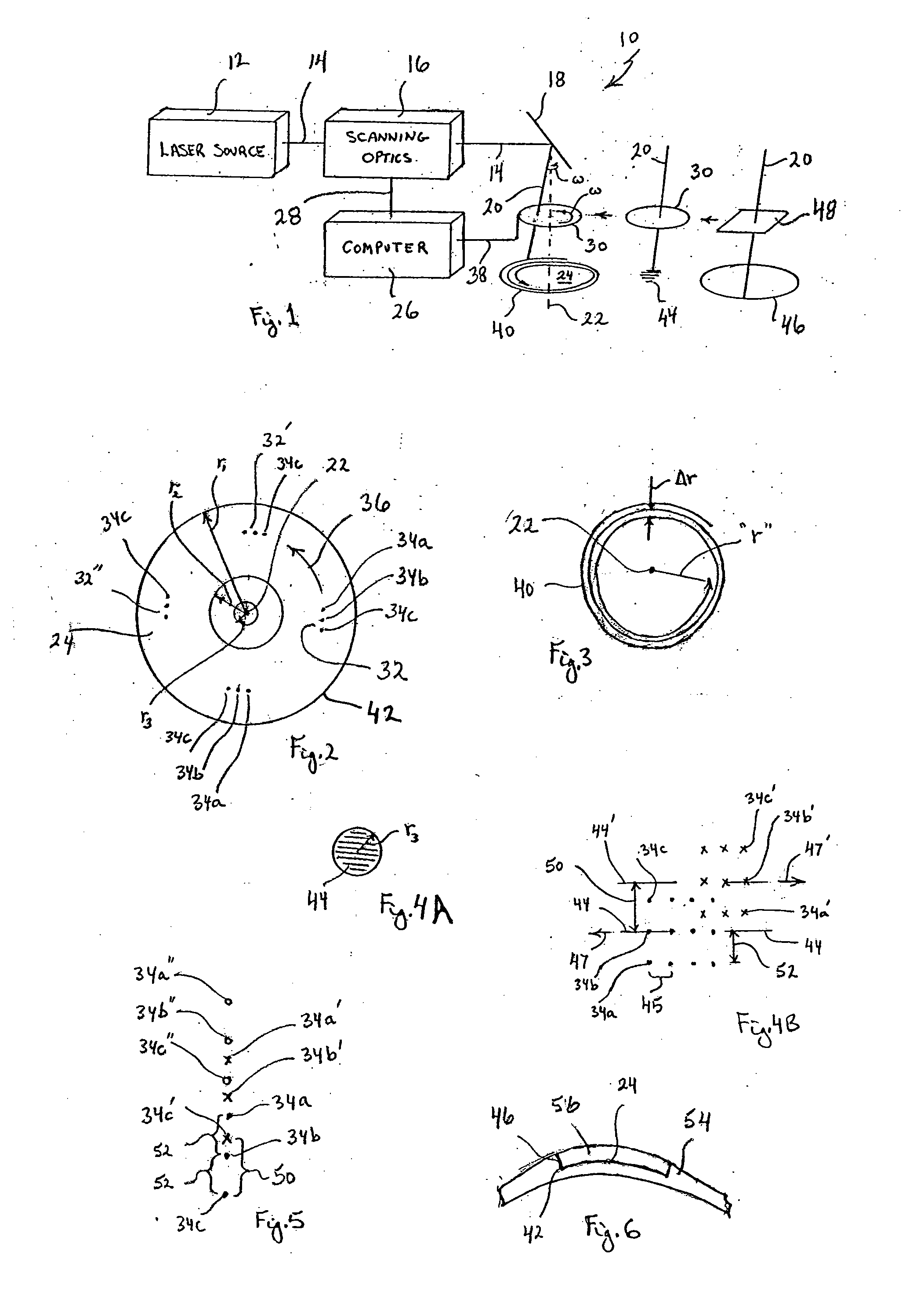
[0025] Referring initially to FIG. 1, a system for performing ophthalmic surgery in accordance with the present invention is shown, and is generally designated 10. In FIG. 1 it will be seen that the system 10 includes a laser source 12 for generating a laser beam 14. As envisioned for the present invention, the laser beam 14 will be pulsed, and will have pulses of femtosecond duration (i.e. less than one picosecond duration). Further, each pulse will have an energy level of approximately 4.5 μJ, and the pulses in laser beam 14 will be generated approximately every 25 μsec.

[0026] Still referring to FIG. 1, the system 10 is shown to include a scanning optics unit 16 and a turning mirror 18. Together, the unit 16 and the turning mirror 18 are used to direct the laser beam 14 along a beam path 20, relative to a central axis 22, and toward a treatment area 24. For purposes of the present invention, the scanning optics unit 16 includes a system of so-called galvo-mirrors (not shown) that...


PUM

PropertyMeasurementUnit
Lengthaaaaaaaaaa
Lengthaaaaaaaaaa
Timeaaaaaaaaaa

Abstract

A system and method for performing ophthalmic surgery requires splitting a laser beam into a pattern having a plurality of focal points. The pattern is then moved along a spiral path according to a predetermined, two-phase protocol. In the first phase, a radial spacing “Δr” between spiral lines, and the velocity of the pattern “rω” are held constant as the radius “r” is decreased from r1 to r2. In the second phase the angular velocity “ω” is held constant and the radial spacing “Δr” is proportionally increased as “r” is further decreased from r2 to r3. Additional LIOB is required both inside r3, as r is reduced to zero and, then, along the periphery of the treatment area for a rim cut at r1.

Description

[0001] This application is a continuation-in-part of pending application Ser. No. 11 / 190,052 filed Jul. 26, 2005, which is a continuation-in-part of pending application Ser. No. 11 / 033,967 filed Jan. 12, 2005, which is a continuation-in-part of application Ser. No. 10 / 293,226, filed Nov. 13, 2002, which issued as U.S. Pat. No. 6,887,232 on May 3, 2005. The contents of application Ser. Nos. 11 / 190,052 and 11 / 033,967, and issued U.S. Pat. No. 6,887,232, are incorporated herein by reference.FIELD OF THE INVENTION [0002] The present invention pertains generally to systems and methods for performing ophthalmic surgery. More particularly, the present invention pertains to systems and methods wherein pulses of a femtosecond laser beam are split into a pattern having a plurality of focal points. The present invention is particularly, but not exclusively, useful for systems and methods wherein the movement and orientation of a focal point pattern are coordinated to maximize the efficiency of...

Claims


Application Information

Patent Timeline
IPC IPC(8): A61B18/18
CPCA61F9/008A61F9/00827A61F9/00836B23K26/0807A61F2009/00897B23K26/067A61F2009/00872B23K26/082
Inventor BILLE, JOSEF
Owner TECHNOLAS PERFECT VISION
Why Eureka
Try Eureka