High order mode electromagnetic wave coupler and coupling method using proportional distributing waves

a technology of electromagnetic waves and coupling methods, applied in coupling devices, waveguide type devices, basic electric elements, etc., can solve problems such as serious mode competition, and achieve the effects of high bandwidth, high conversion efficiency, and high mode purity

Inactive Publication Date: 2007-08-09
NATIONAL TSING HUA UNIVERSITY
View PDF4 Cites 24 Cited by
  • Summary
  • Abstract
  • Description
  • Claims
  • Application Information

AI Technical Summary

Benefits of technology

[0009] The primary objective of the present invention is to provide a high order mode electromagnetic wave coupler using proportional distributing waves. The invention comprises an electromagnetic wave power divider, being comprised of a Y-shaped bifurcated waveguide to divide the wave to one or more orders. The divided wave is proportional so that the electromagnetic wave has a symmetric magnitude after passing through the bifurcated rectangular waveguide, and so that the electromagnetic wave can distribute the waves to a position with a suitable angle after passing through the curved waveguide. The wave is then injected into the mode converter; therefore, the coupler features high converting efficiency, high mode purity, high bandwidth, and convenient operation.
[0012] The present invention provides a new high-efficiency TE01 mode coupler, specifically a high order mode electromagnetic wave coupler and coupling method. The coupler features reduced converting components (main waveguide 21), high converting efficiency (shortened transition length), high mode purity (99.99%), high bandwidth, and convenient operation.
[0013] For example, converting a linear polarized wave from rectangular waveguide TE10 mode to a circular waveguide TE01 mode is based on the above-mentioned principles. The method extends to other high order and microwave guide-shaped mode conversions. The TE01 mode has drawn much attention in a variety of applications, such as Electron Cyclotron Maser (ECM) based gyrotron microwave sources, microwave systems, electromagnetic input and output devices, including microwave equipment, microwave plasma sources, microwave material processing, as well as applications in telecommunications industry and national defense industry. Among a wide range of selection in couplers for microwave, the circular TE01 mode is commonly used due to its features of azimuthally symmetric electric field and low ohmic loss. The TE01 mode in the present invention has high mode purity of 99.9%, and the converting efficiency is 98.5%, which is superior to conventional methods.
[0014] The electromagnetic wave power divider A of the present invention has two Y-shaped bifurcated waveguides 11 to divide the wave to one or more orders. The divided wave is proportional so that the electromagnetic wave has symmetric magnitude after passing through the bifurcated rectangular waveguide 111, and so that the electromagnetic wave can distribute the waves to a position with suitable angle after passing through the curved waveguide 110. Then, the wave is injected into the mode converter B. The coupler features high converting efficiency, high mode purity, high bandwidth, and convenient operation. The coupler can generate multiple coupling modes, TE01, TE21, TE31, TE41, TE51.

Problems solved by technology

However, during the converting process, the waves of the unwanted modes will interact with the electron beam, which will result in serious mode competition.

Method used


Image

  • High order mode electromagnetic wave coupler and coupling method using proportional distributing waves
  • High order mode electromagnetic wave coupler and coupling method using proportional distributing waves
  • High order mode electromagnetic wave coupler and coupling method using proportional distributing waves

Examples


Embodiment Construction

[0029] The features and the advantages of the present invention will be more readily understood upon a thoughtful deliberation of the following detailed description of a preferred embodiment of the present invention with reference to the accompanying drawings.

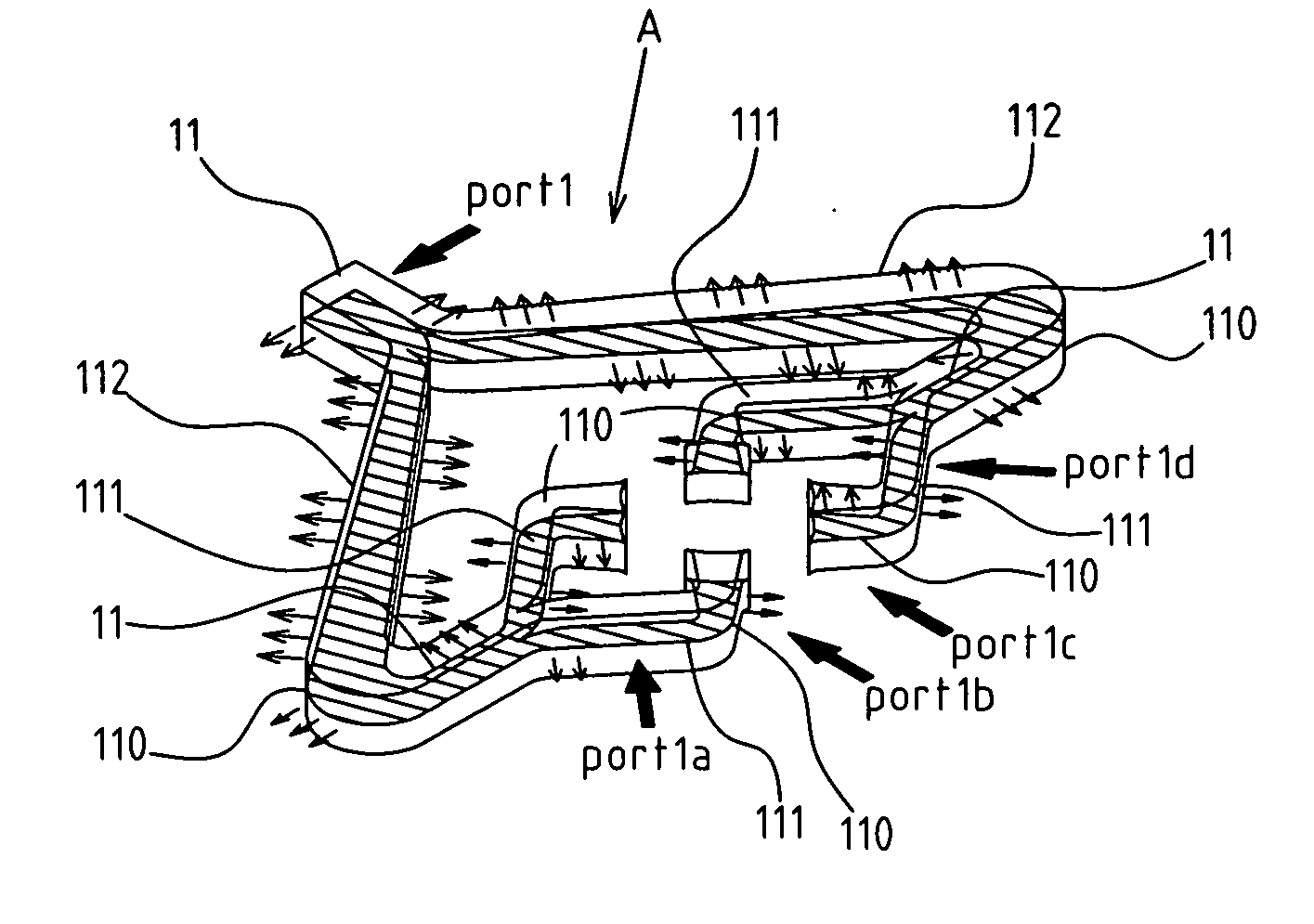
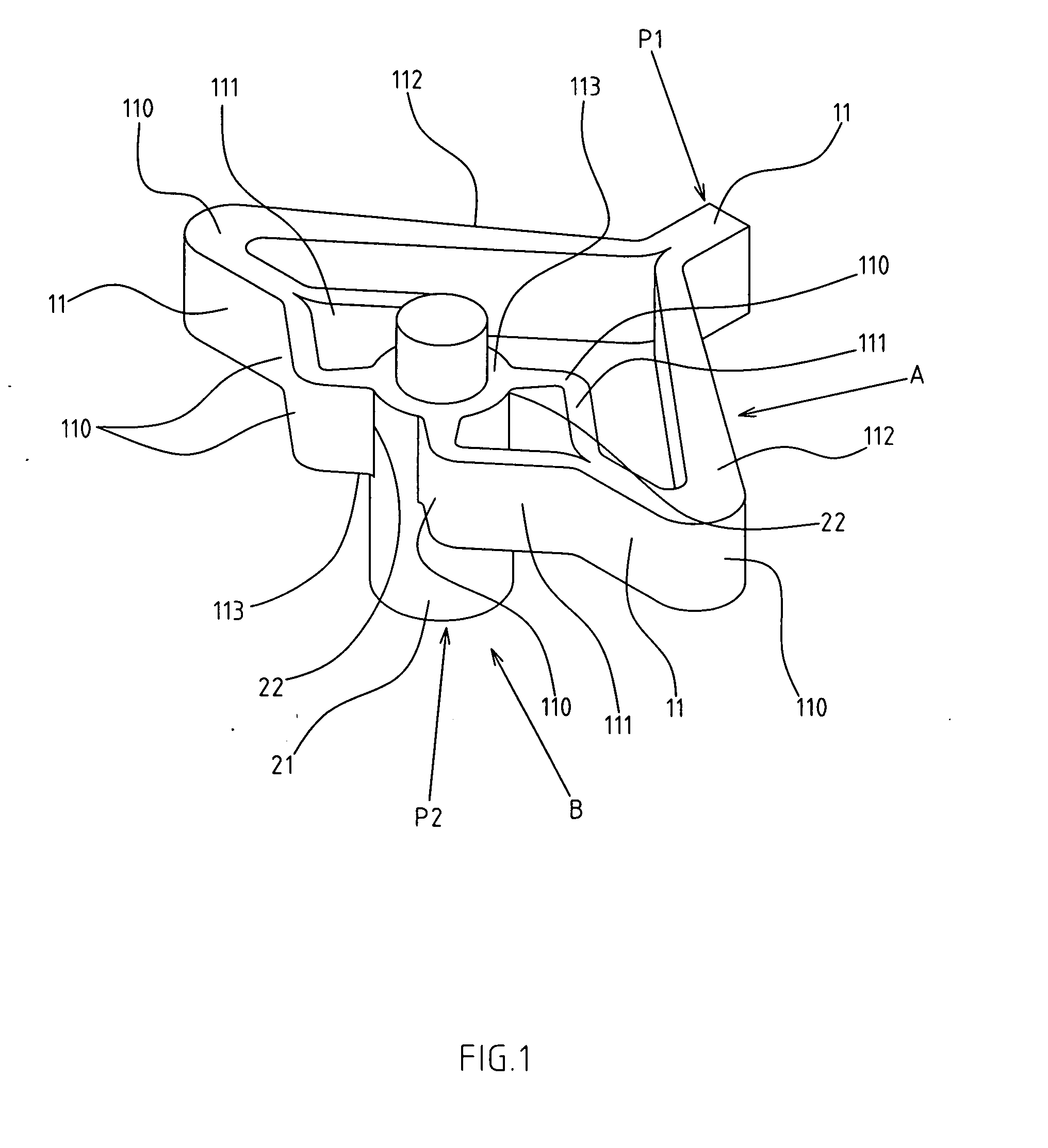
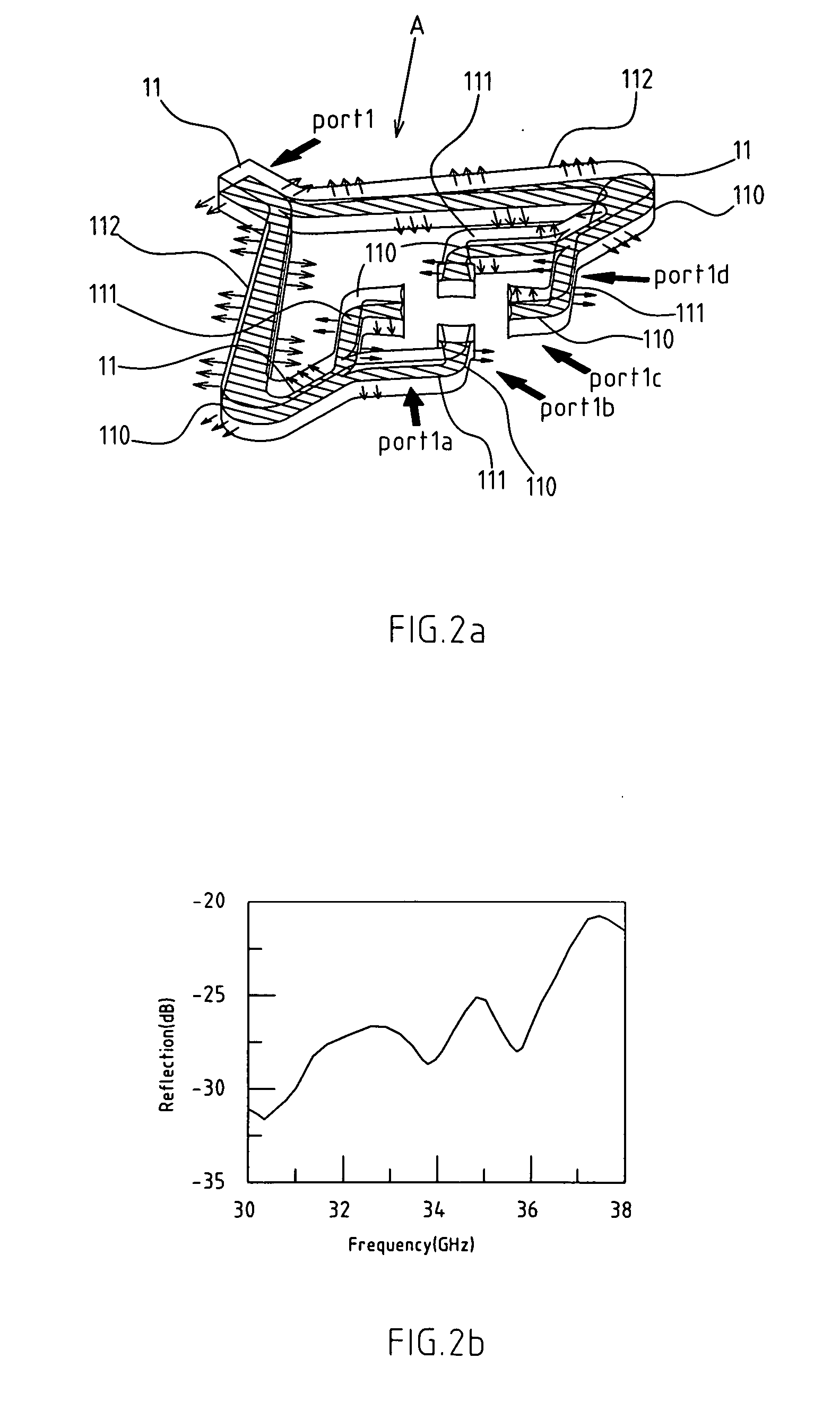
[0030] As shown in FIG. 1, there a high order mode electromagnetic wave coupler using proportional distributing waves.

[0031] The invention includes an electromagnetic wave power divider A, which has one or more Y-shaped bifurcated waveguides 11 to divide the wave to one or more orders. The input end of the Y-shaped bifurcated waveguide 11 is a rectangular waveguide, and the other end is split into two rectangular waveguides. Each Y-shaped bifurcated waveguide 11 is connected to the power divider by a curved waveguide 110. The divided wave is proportional so that the electromagnetic wave has symmetric magnitude after passing through the bifurcated rectangular waveguide 111, and so that the electromagnetic wave can distribute t...


PUM


Abstract

The high order mode electromagnetic wave coupler and coupling method uses one or more Y-shaped bifurcated waveguides to divide the wave to one or more order, so as to divide the target electromagnetic wave proportionally into equal shares. The waveguide is used to inject the electromagnetic wave to a main waveguide, so that the electromagnetic wave is converted into high order mode in the main waveguide. For example, a rectangular waveguide TE10 mode can be converted to a circular TE01 mode, wherein this conversion can also be applied to higher order modes and microwave guide-shaped modes. The coupling method includes a electromagnetic wave power dividing section and mode converting section, of which the power divider and dividing method can divide the electromagnetic wave proportionally. The coupler and coupling method feature high converting efficiency, high mode purity, high bandwidth, and convenient operation.

Description

RELATED U.S. APPLICATIONS [0001] Not applicable. STATEMENT REGARDING FEDERALLY SPONSORED RESEARCH OR DEVELOPMENT [0002] Not applicable. REFERENCE TO MICROFICHE APPENDIX [0003] Not applicable. FIELD OF THE INVENTION [0004] The present invention relates generally to a high order mode electromagnetic wave coupler and coupling method using proportional distributing waves, and more particularly to a coupling technology that converts the rectangular waveguide TE10 mode to the circular waveguide TE01 mode. BACKGROUND OF THE INVENTION [0005] The TE01 mode, having advantages of field azimuthal symmetry and low propagating loss, is widely used in microwave applications, such as in gyrotron microwave sources. When applied to microwave plasma heating, the symmetrical distribution of the circular TE01 mode is expected to make heating more evenly. [0006] Two methods have been classified to generate the TE01 mode with a cylindrical waveguide. One method is in-line coupling, and another is sidewall...

Claims


Application Information

Patent Timeline
Patent Type & Authority Applications(United States)
IPC IPC(8): H01P5/12
CPCH01P5/082
Inventor CHANG, TSUN-HSUYU, CHING-FANG
Owner NATIONAL TSING HUA UNIVERSITY
Why Eureka
Try Eureka