High performance hybrid magnetic structure for biotechnology applications

a hybrid magnetic structure, biotechnology technology, applied in the direction of magnetic bodies, laboratory glassware, instruments, etc., can solve the problems of inability to apply biotechnology applications, inability to achieve high-performance hybrid magnetic structures, poor results, etc., to achieve sufficient cross section, improve the field strength of selected poles, and improve the hybrid magnetic structure

Inactive Publication Date: 2007-08-09
RGT UNIV OF CALIFORNIA
View PDF2 Cites 40 Cited by
  • Summary
  • Abstract
  • Description
  • Claims
  • Application Information

AI Technical Summary

Benefits of technology

[0041] The field strengths of selected poles and the hybrid magnetic structure can be improved by a return yoke. In one embodiment, the return yoke is a flux conduit having sufficient cross section to avoid saturation and wherein the return yoke is sufficient distance from the bottom of the hybrid magnetic structure to avoid significant magnetic interaction. In another embodiment, the return yoke is a shield to minimize strong fields below the hybrid magnetic structure.
[0042] The hybrid magnetic structure can further comprise a protective cover which magnetically attaches to the top of the magnetic structure to prevent unwanted interaction with another hybrid magnetic structure or magnetic material and to provide a surface for warning against bodily injury.

Problems solved by technology

The imbalance in moments is caused by the presence of Fe ions with different oxidation states.
Hybrid magnetic technology has been widely known and used in the accelerator community, however, it has not been applied to any biotechnology application thus far.
Previous technology produces weak fields and gradients that give poorer results and long separation times.
The design as shown by Howe et al. is limited in terms of field increases from vertical scaling.
Furthermore, the fundamental design of the Howe magnetic structure is not capable of producing the level of field strength that can be produced by the current invention.

Method used


Image

  • High performance hybrid magnetic structure for biotechnology applications
  • High performance hybrid magnetic structure for biotechnology applications
  • High performance hybrid magnetic structure for biotechnology applications

Examples


example 1

[0155] Hybrid Magnetic Structure for Use with 96- and 384-Well Microtiter Plates

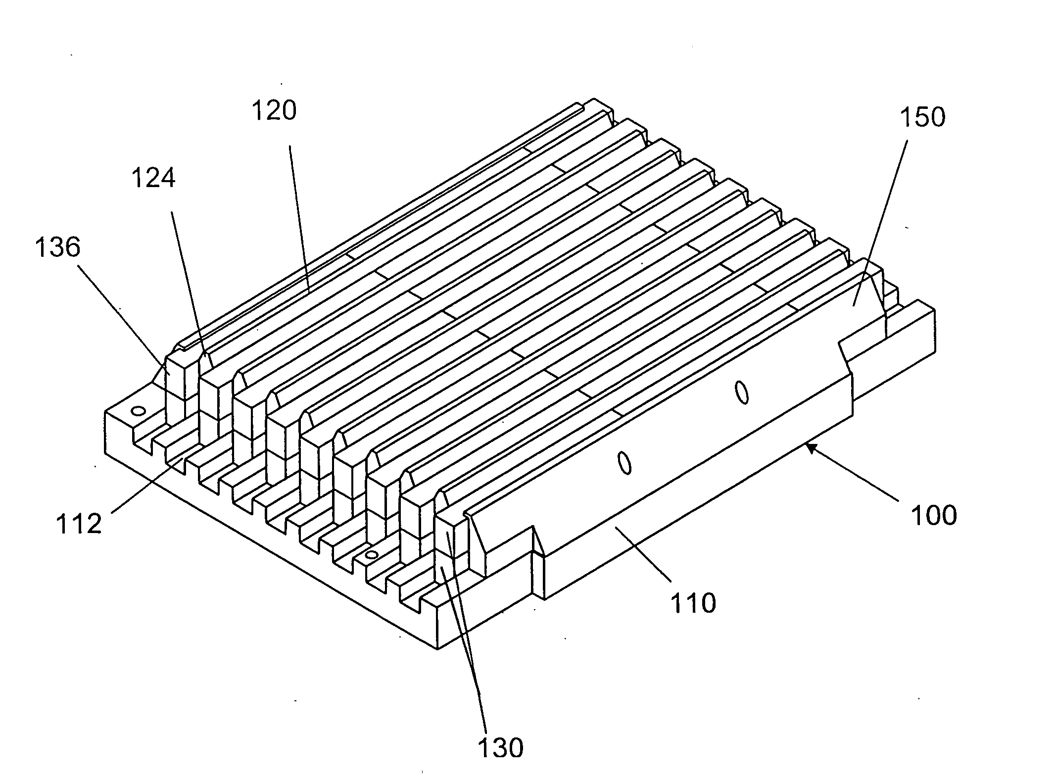
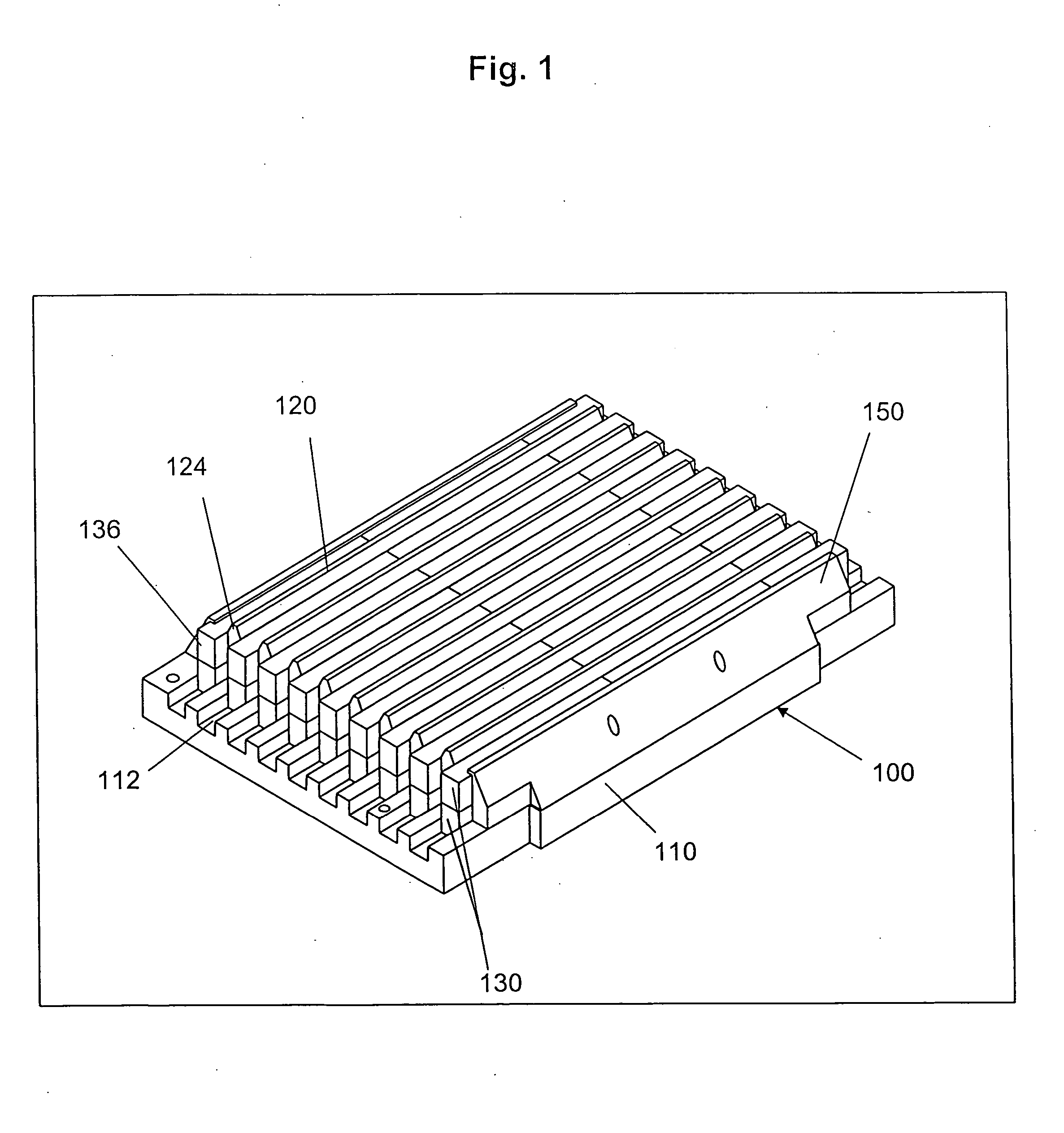
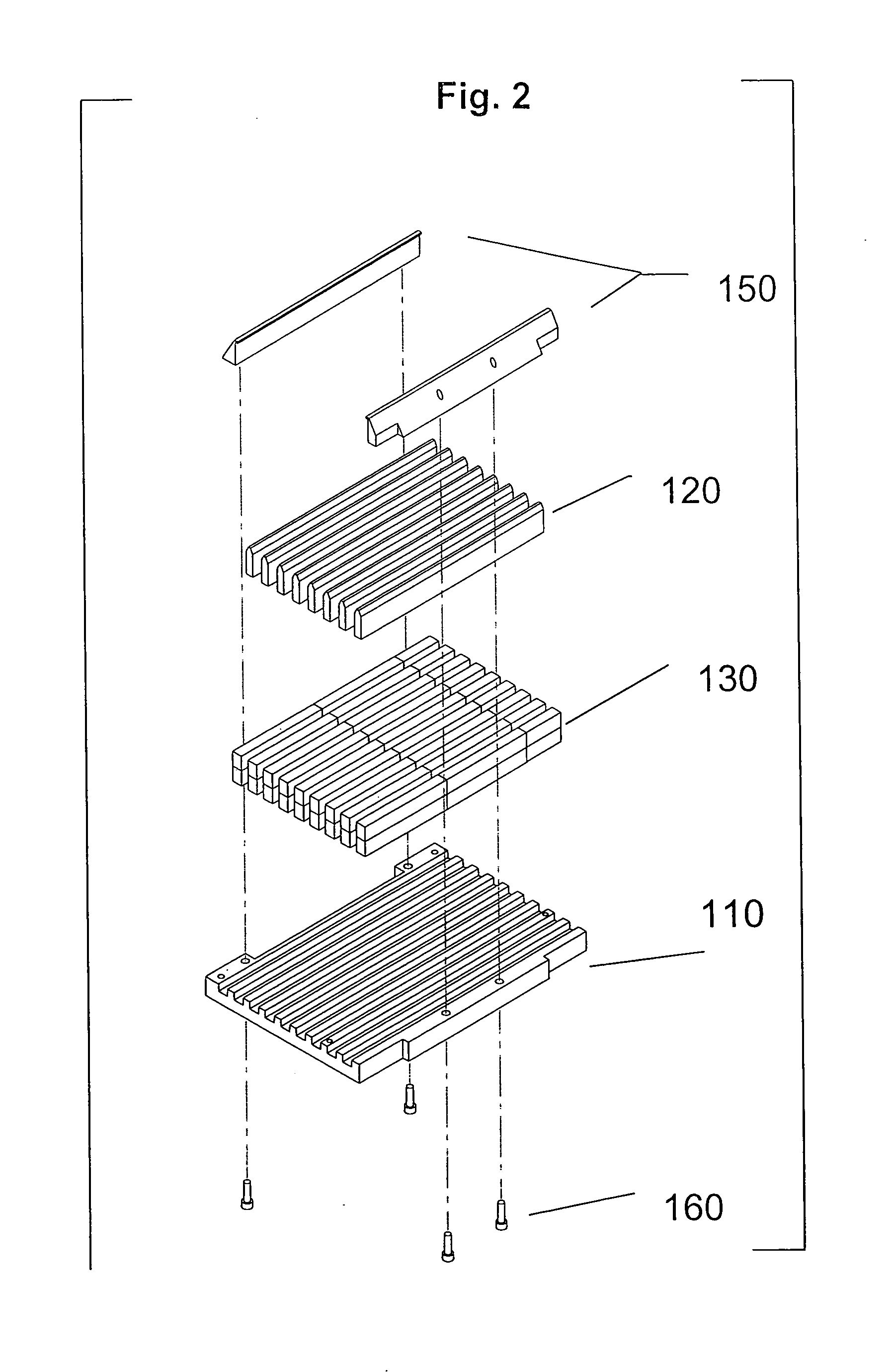
[0156] Referring now to FIGS. 1 and 2, shown is a preferred embodiment of the hybrid magnetic structure for applications involving 96- or 384-well microtiter plates. FIGS. 1 and 2 show the design adopted for the preferred core assembly 100. The machined base plate 110, which was fashioned from aluminum and then clear anodized, was made 5.3 inches×3.64 inches wide×0.375 inches tall to permit a standard microtiter plate to be seated comfortably atop the hybrid magnet structure. The base 110 has 9 slots or grooves 112 to allow a block or blocks of permanent magnet material 130 to sit in each slot. The eight soft ferromagnetic poles 120 sit on the raised spacings between the slots 112. One long notch was created on one long side of the base 110. Two smaller notches were made, one at each end of the opposite long side. This was done to create an asymmetric base plate with a front side and a back side, which ...

example 2

[0162] 2-D Modeling of Magnetic Structures

[0163] Referring now to FIG. 4, two and three dimensional computer models were constructed to further develop and quantify performance of one embodiment of the hybrid magnetic structure. The field plot shown in FIG. 4 is a 2-D boundary value model solved by the code PANDIRA which is a member of the POISSON SUPERFISH codes. The axes of FIG. 4 are in centimeters. The left side of the model is a Dirichlet boundary and implies mirror image symmetry. The model shown has a geometric periodicity of 0.9 cm which is the distance from the center of one pole to the center of the next pole. The magnetic periodicity is twice that or 1.8 cm. Because of the left hand Dirichlet symmetry boundary, the model is a complete representation of an infinitely long structure having three full magnetic periods. The open boundaries at the right of the structure allow complete modeling of the truncation or end-effect fields.

[0164] The field lines shown are lines of c...

example 3

[0166] Field Strength Comparison Test

[0167] Referring now to FIG. 5, the fields of the high performance hybrid magnetic structure of Example 1 are both stronger and extend farther than those of any commercial magnetic plates tested. The invention produces fields and gradients that are up to four times greater than previous industry-standard magnet plates and a more beneficial field distribution for a number of important applications.

[0168] Relative field strengths of five or six different magnet structures are given in FIGS. 5A and 5B. Four of the magnet structures (with “LBL” designation) were developed at Joint Genome Institute / Lawrence Berkeley National Laboratory. The other two are currently available commercially magnet plates. The field strength was measured at two heights, close (less than 0.5 mm) to the magnet structure surface (FIG. 5A) and at 1 cm above the magnet structure surface (FIG. 5B). Measurements were made using a commercially available Hall effect probe. The st...


PUM

PropertyMeasurementUnit
diameteraaaaaaaaaa
magnetic period lengthaaaaaaaaaa

Abstract

The present disclosure provides a high performance hybrid magnetic structure made from a combination of permanent magnets and ferromagnetic pole materials which are assembled in a predetermined array. The hybrid magnetic structure provides means for separation and other biotechnology applications involving holding, manipulation, or separation of magnetic or magnetizable molecular structures and targets. Also disclosed are further improvements to aspects of the hybrid magnetic structure, including additional elements and for adapting the use of the hybrid magnetic structure for use in biotechnology and high throughput processes.

Description

CROSS-REFERENCE TO RELATED APPLICATIONS [0001] This application claims priority to and is a continuation-in-part of U.S. patent application Ser. No. 11 / 248,934, filed Oct. 11, 2005, now allowed and to be issued, which is a continuation-in-part of U.S. Ser. No. 10 / 305,658, filed Nov. 26, 2002, now U.S. Pat. No. 6,954,128, which claims priority from U.S. Provisional Application No. 60 / 335,226, filed Nov. 30, 2001, each of which are hereby incorporated by reference in their entirety.STATEMENT OF GOVERNMENTAL SUPPORT [0002] This invention was made during work supported by U.S. Department of Energy under Contract No. DE-AC03-76SF00098, now DE-AC02-05CH11231. The government has certain rights in this invention.BACKGROUND OF THE INVENTION [0003] 1. Field of the Invention [0004] The present invention relates to magnetic separation, concentration and other biotechnology applications involving holding, concentration, manipulation or separation of magnetic or magnetizable molecular structures ...

Claims


Application Information

Patent Timeline
Patent Type & Authority Applications(United States)
IPC IPC(8): H01F7/02
CPCH01F7/0252B03C1/0332B03C1/288B03C2201/18B03C2201/22B03C2201/26B01L3/5085B01L2300/0829
Inventor HUMPHRIES, DAVID E.POLLARD, MARTIN J.ELKIN, CHRISTOPHER J.
Owner RGT UNIV OF CALIFORNIA
Why Eureka
Try Eureka