Apparatus and method for driving liquid crystal display device

a liquid crystal display and apparatus technology, applied in the direction of general fasteners, instruments, computing, etc., can solve the problems of low light efficiency and difficulty in high-resolution color realization ratio, and achieve the effect of improving the color realization ratio of the lcd panel

Active Publication Date: 2007-08-09
LG DISPLAY CO LTD
View PDF7 Cites 60 Cited by
  • Summary
  • Abstract
  • Description
  • Claims
  • Application Information

AI Technical Summary

Benefits of technology

[0014]Accordingly, the present embodiments are directed to an apparatus and method for driving an LCD device, which may obviate one or more problems due to limitations and disadvantages of the related art. For example, one embodiment improves a color realization ratio of an LCD panel using an LED backlight unit comprised of LEDs of at least five colors.

Problems solved by technology

If the electric field is applied along one direction to the liquid crystal layer for a long time, it may cause deterioration.
The related art LCD device includes a unit pixel provided with dots of red(R), green(G) and blue(B) colors, and m a y have a problem of low light-efficiency.
The RGBW-type LCD device displays the color image by using the red, green, blue and white light so that it is difficult to highly improve the color realization ratio.

Method used


Image

  • Apparatus and method for driving liquid crystal display device
  • Apparatus and method for driving liquid crystal display device
  • Apparatus and method for driving liquid crystal display device

Examples


first embodiment

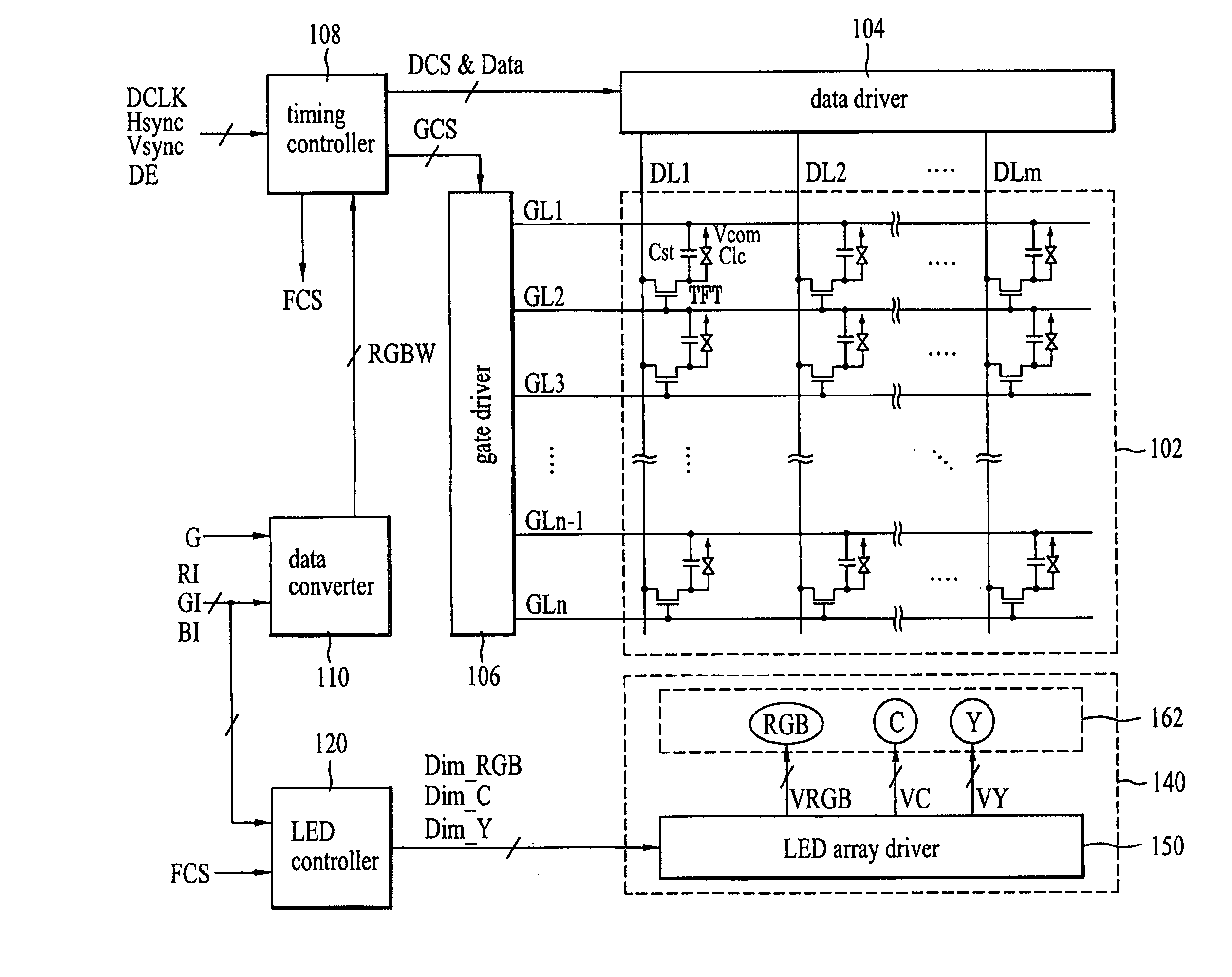
[0040]In a first embodiment, as shown in FIGS. 4 and 5, an apparatus for driving the LCD device a includes an LCD panel 102 which includes liquid crystal cells formed in respective sub-pixels of four colors defined by n gate lines (GLl to GLn) and m data lines (DLl to DLm). A data driver 104 supplies a video signal to the data lines (DLl to DLm). A gate driver 106 supplies a scan pulse to the gate lines (GLl to GLn). A data converter 110 converts input data of three colors (RI, GI, BI) to input data of four colors (RGBW). A timing controller 108 arranges the input data of four colors (RGBW) in four-color data (Data) for three sub-frames and then supplies the arranged data to the data driver 104, and generates a sub-frame control signal (FCS) corresponding to each sub-frame. An LED backlight unit 140 includes LEDs of five colors to emit the light to the LCD panel 102. An LED controller 120 controls the LED backlight unit 140 in accordance with the input data of three colors (RI, GI, ...

second embodiment

[0081]In one embodiment, as shown in FIGS. 10 and 11, the apparatus for driving the LCD device includes an LCD panel 102 that includes liquid crystal cells formed in respective sub-pixels of four colors defined by n gate lines (GLl to GLn) and m data lines (DL1 to DLm). A data driver 104 supplies a video signal to the data lines (DL1 to DLm). A gate driver 106 supplies a scan pulse to the gate lines (GL1 to GLn). A data converter 110 converts input data of three colors (RI, GI, BI) to input data of four colors (RGBW). A timing controller 308 arranges the input data of four colors (RGBW) supplied from the data converter 110 by each frame in four-color data (Data) for four sub-frames and then supplies the arranged data to the data driver 104, and generates a sub-frame control signal (FCS) corresponding to each sub-frame. An LED backlight unit 340 includes LEDs of six colors that emit the light to the LCD panel 102. An LED controller 320 controls the LED backlight unit 340 in accordan...

third embodiment

[0108]In a third embodiment, as shown in FIG. 14, the apparatus for driving the LCD device a includes an LCD panel 102 which is comprised of liquid crystal cells formed in respective sub-pixels of four colors defined by n gate lines (GL1 to GLn) and m data lines (DL1 to DLm). A data driver 104 supplies a video signal to the data lines (DL1 to DLm). A gate driver 106 supplies a scan pulse to the gate lines (GL1 to GLn). A data converter 110 converts input data of three colors (RI, GI, BI) to input data of four colors (RGBW). A timing controller 108 arranges the input data of four colors (RGBW) supplied from the data converter 110 by each frame in four-color data (Data) for three sub-frames and then supplies the arranged data to the data driver 104, and generates a sub-frame control signal (FCS) corresponding to each sub-frame. A backlight unit 540 includes a lamp 566 and LEDs of two colors (C, Y) to emit the light to the LCD panel 102. A backlight controller 520 controls the backligh...


PUM


Abstract

An apparatus and method for driving an LCD device is provided. The apparatus includes an LCD panel that is comprised of red, green, blue and white sub-pixels. A data converter converts input data of three colors into input data of four colors. A data driver converts the input data of four colors into a video signal, and supplies the video signal to each sub-pixel. A gate driver supplies a scan pulse to each sub-pixel. A timing controller arranges the input data of four colors supplied from the data converter and then supplies the arranged data to the data driver. A backlight unit is comprised of LEDs of at least five colors to emit the light to the LCD panel. A backlight controller controls the backlight unit in accordance with the input data of three colors and the sub-frame control signal.

Description

[0001]This application claims the benefit of the Korean Patent Application No. P2006-0012638, filed on Feb. 9, 2006, which is hereby incorporated by reference as if fully set forth herein.BACKGROUND[0002]The present embodiments relate to an apparatus and method for driving an LCD device.RELATED ART [0003]Generally, an LCD device displays an image on an LCD panel by controlling transmittance of light provided from a backlight unit. The LCD panel is provided with a plurality of liquid crystal cells arranged in a matrix configuration, and a plurality of control switches to switch a video signal supplied to the liquid crystal cells.[0004]The LCD device includes a liquid crystal layer in which an electric field is formed in accordance with a data signal, to thereby display the desired image by controlling the transmittance of light passing through the liquid crystal layer. If the electric field is applied along one direction to the liquid crystal layer for a long time, it may cause deter...

Claims


Application Information

Patent Timeline
Patent Type & Authority Applications(United States)
IPC IPC(8): G09G3/36
CPCG02F2001/133613G09G3/3413G09G2340/06G09G3/3648G09G2320/064G09G3/3426G02F1/133613A44B11/06A44B11/001A44D2211/00
Inventor HONG, HEE JUNGKWON, KYUNG JOON
Owner LG DISPLAY CO LTD
Why Eureka
Try Eureka