Liquid crystal diffraction lens element and optical head device

Inactive Publication Date: 2007-08-09
ASAHI GLASS CO LTD
View PDF10 Cites 113 Cited by
  • Summary
  • Abstract
  • Description
  • Claims
  • Application Information

AI Technical Summary

Benefits of technology

[0027] 8. The liquid crystal diffraction lens element according to any one of the above 1 to 7, wherein a part of each of the birefringent Fresnel lens members is made of an isotropic material.
[0028] According to this construction, besides any one of the effects of the above 1 to 7, it becomes possible to adjust birefringent index of entire Fresnel lens member made of an isotropic material and a birefringent material, and it is possible to realize a liquid crystal diffraction lens element having high design flexibility since there are many variations of the birefringent material and the liquid crystal to be used.
[0029] 9. The liquid crystal diffraction lens element according to any one of the above 1 to 8, wherein a phase adjustment surface of concave-convex shape is integrated with at least one of the transparent substrates.
[0030] According to this construction, besides any one of the effects of the constructions of the above 1 to 8, since the phase adjustment surface can produc

Problems solved by technology

However, in such a conventional optical head device, since the liquid crystal in the optical modulation element is uniformly aligned, there has been a problem that for light polarized in a direction in which the liquid crystal shows the ordinary refractive index, the refractive index of the liquid crystal can not be switched by switching

Method used


Image

  • Liquid crystal diffraction lens element and optical head device
  • Liquid crystal diffraction lens element and optical head device
  • Liquid crystal diffraction lens element and optical head device

Examples


first embodiment

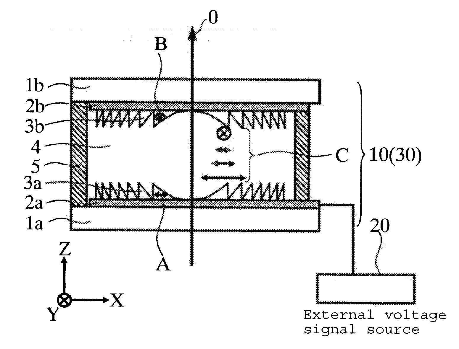
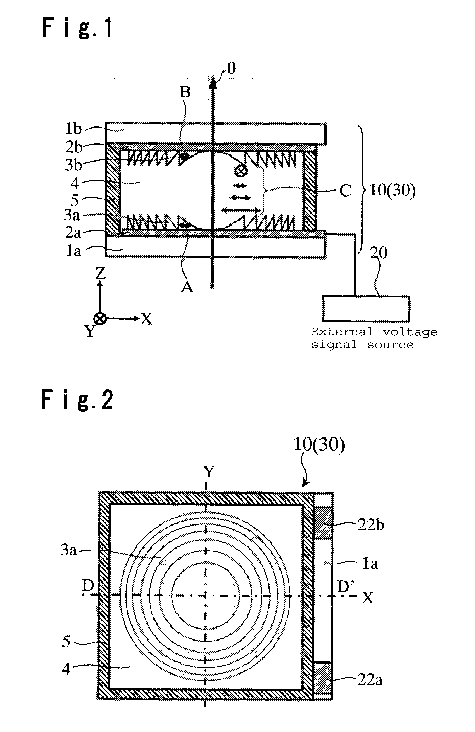
[0046]FIG. 1 and FIG. 2 are respectively a cross sectional view and a plan view showing a conceptual construction of a liquid crystal diffraction lens element according to the first embodiment of the present invention. The cross sectional view shown in FIG. 1 shows a D-D′ cross section of the liquid crystal diffraction lens element shown in FIG. 2. In FIG. 1 and FIG. 2, the liquid crystal diffraction lens element 10 comprises a pair of transparent substrates 1a, 1b disposed in parallel, a liquid crystal 4 sandwiched between the pair of transparent substrates 1a and 1b, transparent electrodes 2a, 2b for applying an electric field to the liquid crystal, a first birefringent Fresnel lens member 3a formed between the first transparent substrate 1a and the liquid crystal 4, having a Fresnel lens shape and made of a birefringent material, a second birefringent Fresnel lens member 3b formed between the second transparent substrate 1b opposed to the first transparent substrate 1a and the li...

second embodiment

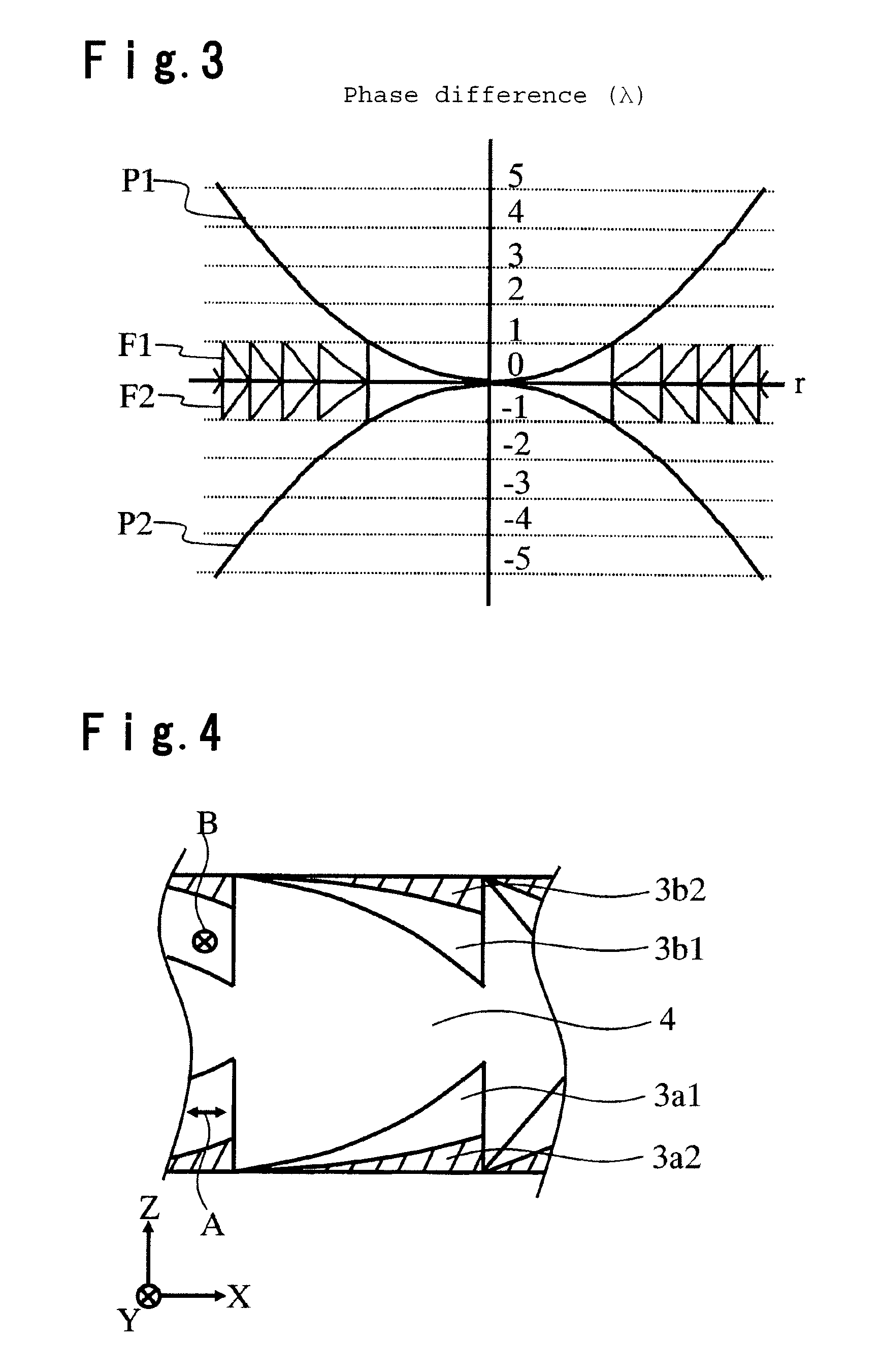
[0069] The liquid crystal diffraction lens element 10 according to the first embodiment employs birefringent Fresnel lens members 3a and 3b made of a birefringent material and a liquid crystal 4, and has a construction that the refractive indexes (no, ne) of the birefringent material agree with the refractive indexes (nlo, nle) of the liquid crystal 4. By this construction, when no voltages applied, light propagating in Z axis direction is, regardless of its polarization direction, transmitted through the liquid crystal diffraction lens element without generating diffraction light, and when a voltage is applied, the liquid crystal 4 is aligned in Z axis direction, and light propagating in Z axis direction receives the effects of the birefringent Fresnel lens members 3a and 3b to be divergent light or converging light and transmitted through the liquid crystal diffraction lens element 10.

[0070] However, it is difficult to make the refractive indexes (no, ne) of the birefringent mate...

third embodiment

[0096] Then, an optical head device according to the third embodiment of the present invention is described with reference to drawings. FIG. 7 is a view showing a conceptual construction of an optical head device according to an embodiment of the present invention. In FIG. 7, an optical head device 100 comprises a light source 101 emitting a light flux of predetermined wavelength, a polarizing beam splitter 102 transmitting or reflecting light according to polarization direction of the light, a collimator lens 103 transforming incident light flux into substantially parallel light, a liquid crystal diffraction lens element 10, a quarter wavelength plate 104, an objective lens 105 for converging light transmitted through the quarter wavelength plate 104 on an optical disk 200, and a photodetector 106 for detecting returning light from the optical disk 200 reflected by the polarizing beam splitter 102. Here, the “returning light” means light emitted from the light source 101, reflected...


PUM


Abstract

A liquid crystal diffraction lens element and an optical head device, which can switch focal lengths of both of outgoing light and returning light by a single element, are provided.
The liquid crystal lens element comprises transparent substrates 1a, 1b, a liquid crystal 4 sandwiched between the transparent substrates 1a, 1b, transparent electrodes 2a, 2b, birefringent Fresnel lens members 3a, 3b each having a Fresnel lens shape and made of a birefringent material, and a seal 5, wherein the extraordinary refractive index direction A of the birefringent Fresnel lens member 3a and the extraordinary refractive index direction B of the birefringent Fresnel lens member 3b are perpendicular to each other, and the alignment direction of the liquid crystal 4 at the interface between the liquid crystal 4 and the transparent substrate 1a is perpendicular to the alignment direction of the liquid crystal 4 at the interface between the liquid crystal 4 and the transparent substrate 1b.

Description

BACKGROUND OF THE INVENTION [0001] 1. Field of the Invention [0002] The present invention relates to a liquid crystal diffraction lens element capable of switching a focal point, and to an optical head device employing the liquid crystal diffraction lens element for writing and / or reading (hereinafter referred to as writing / reading) an information to / from an optical recording medium such as an optical disk. [0003] 2. Discussion of Background [0004] Heretofore, an optical head device for writing / reading an optical recording medium such as an optical disk, carries out writing / reading an information to / from optical disks having different cover thicknesses such as CD and DVD. Here, between optical disks having different cover thicknesses, the depths of their information recording planes for recording an information, from their disk surfaces (hereinafter simply referred to as the depth of information recording plane) are different. In order to enable writing / reading of a plurality of opt...

Claims


Application Information

Patent Timeline
IPC IPC(8): G02F1/13G11B7/135
CPCG02B3/08G02B3/14G02B5/1866G02B5/1876G02F1/133526G11B2007/0006G02F2001/294G11B7/1353G11B7/1369G11B7/1378G11B7/13925G02F1/29G02F1/294G02F1/13G02B5/18
Inventor OSAWA, MITSUOOOI, YOSHIHARU
Owner ASAHI GLASS CO LTD
Why Eureka
Try Eureka