Adaptive variable length pulse synchronizer

Active Publication Date: 2007-08-09
NXP USA INC
View PDF8 Cites 7 Cited by
  • Summary
  • Abstract
  • Description
  • Claims
  • Application Information

AI Technical Summary

Problems solved by technology

Digital logic which uses a rigid synchronizer design is not able to guarantee capture of spurious and unpredictable analog data when used for different chips using different clock signals, processes, temperatures and voltages.
Existing schemes are unable to ensure detection of an asynchronous pulse that is faster than the reference clock used by the digital logic.

Method used


Image

  • Adaptive variable length pulse synchronizer
  • Adaptive variable length pulse synchronizer
  • Adaptive variable length pulse synchronizer

Examples


Embodiment Construction

[0012] The following description is presented to enable one of ordinary skill in the art to make and use the present invention as provided within the context of a particular application and its requirements. Various modifications to the preferred embodiment will, however, be apparent to one skilled in the art, and the general principles defined herein may be applied to other embodiments. Therefore, the present invention is not intended to be limited to the particular embodiments shown and described herein, but is to be accorded the widest scope consistent with the principles and novel features herein disclosed.

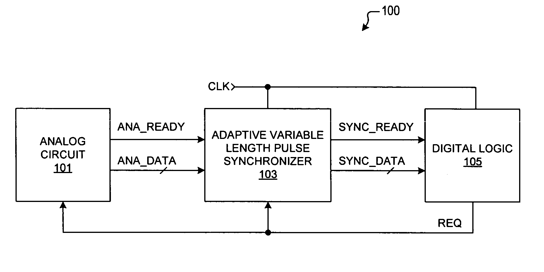
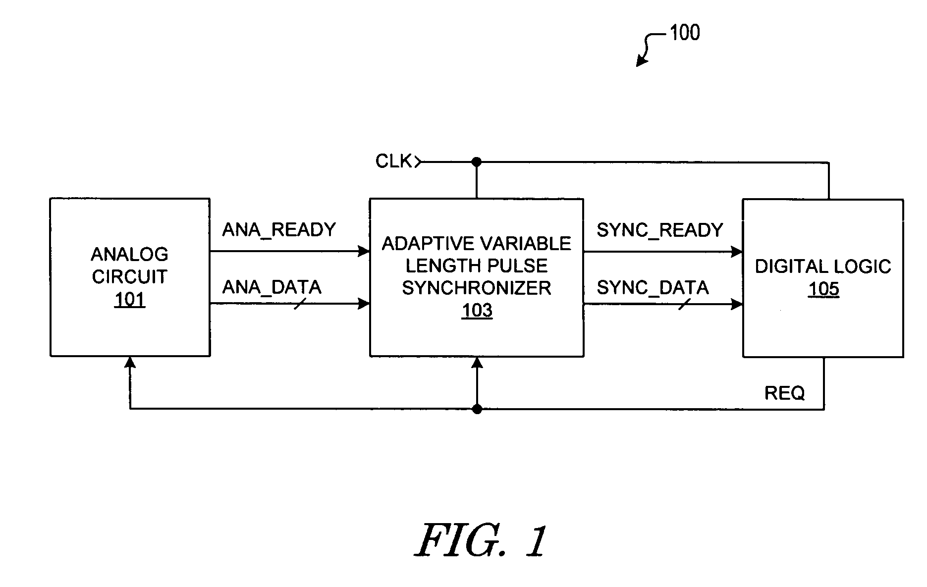
[0013]FIG. 1 is simplified block diagram of a communication system 100 including an adaptive variable length pulse synchronizer 103 implemented according to an embodiment of the present invention. An analog circuit 101 receives a data request signal referred to as REQ and provides an analog data ready signal ANA_READY and one or more analog data signals ANA_DATA. The ANA_DATA...


PUM


Abstract

An adaptive variable length pulse synchronizer including a state keeper circuit, an asynchronous pulse edge detection circuit, a data synchronization circuit, and a pulse edge synchronization circuit. The state keeper circuit detects a leading edge of the asynchronous pulse. The asynchronous pulse edge detection circuit detects a trailing edge of the asynchronous pulse after the state keeper circuit has detected the leading edge. The asynchronous pulse edge detection circuit further provides a pulse synchronized with a clock signal after the asynchronous pulse has been detected. The data synchronization circuit latches the asynchronous data and provides the synchronous data in response to the synchronous pulse. The pulse edge synchronization provides the synchronous ready signal after synchronous data has been provided. In one embodiment, the synchronous pulse occurs between successive rising edges of the clock whereas the synchronous ready signal is provided in response to the intermediate falling edge of the clock.

Description

BACKGROUND OF THE INVENTION [0001] 1. Field of the Invention [0002] The present invention relates in general to data communications, and more specifically to a system and method which captures and synchronizes an asynchronous signal with unknown length and occurrence to a digital clock having any rate or a variable rate. [0003] 2. Description of the Related Art [0004] The time that is needed to generate valid output data provided by an asynchronous analog block varies over process, voltage, and temperature. The output data provided by an asynchronous block must be synchronized with a digital logic clock signal in order for the data to be captured and stored correctly by the digital logic. The clock rate that is used by the digital logic to capture the analog output data, however, varies for different applications. Digital logic which uses a rigid synchronizer design is not able to guarantee capture of spurious and unpredictable analog data when used for different chips using differe...

Claims


Application Information

Patent Timeline
IPC IPC(8): H04L25/38
CPCH04L25/38H04L7/0008
Inventor ANGELLO, JOHN E.AKELLA, SATYAVATHIKASE, KIYOSHILEN, MAY
Owner NXP USA INC
Why Eureka
Try Eureka