Carbon nanostructures and process for the production of carbon-based nanotubes, nanofibres and nanostructures

a carbon nanotube and nanofibre technology, applied in the direction of physical/chemical process catalysts, metal/metal-oxide/metal-hydroxide catalysts, fullerenes, etc., can solve the problem of not being able to obtain the quantity of carbon nanotubes necessary for practical technology

Inactive Publication Date: 2007-08-09
ТІМКАЛ SА +1
View PDF6 Cites 107 Cited by
  • Summary
  • Abstract
  • Description
  • Claims
  • Application Information

AI Technical Summary

Problems solved by technology

The availability of these carbon nanotubes in quantit

Method used


Image

  • Carbon nanostructures and process for the production of carbon-based nanotubes, nanofibres and nanostructures
  • Carbon nanostructures and process for the production of carbon-based nanotubes, nanofibres and nanostructures
  • Carbon nanostructures and process for the production of carbon-based nanotubes, nanofibres and nanostructures

Examples


example 1

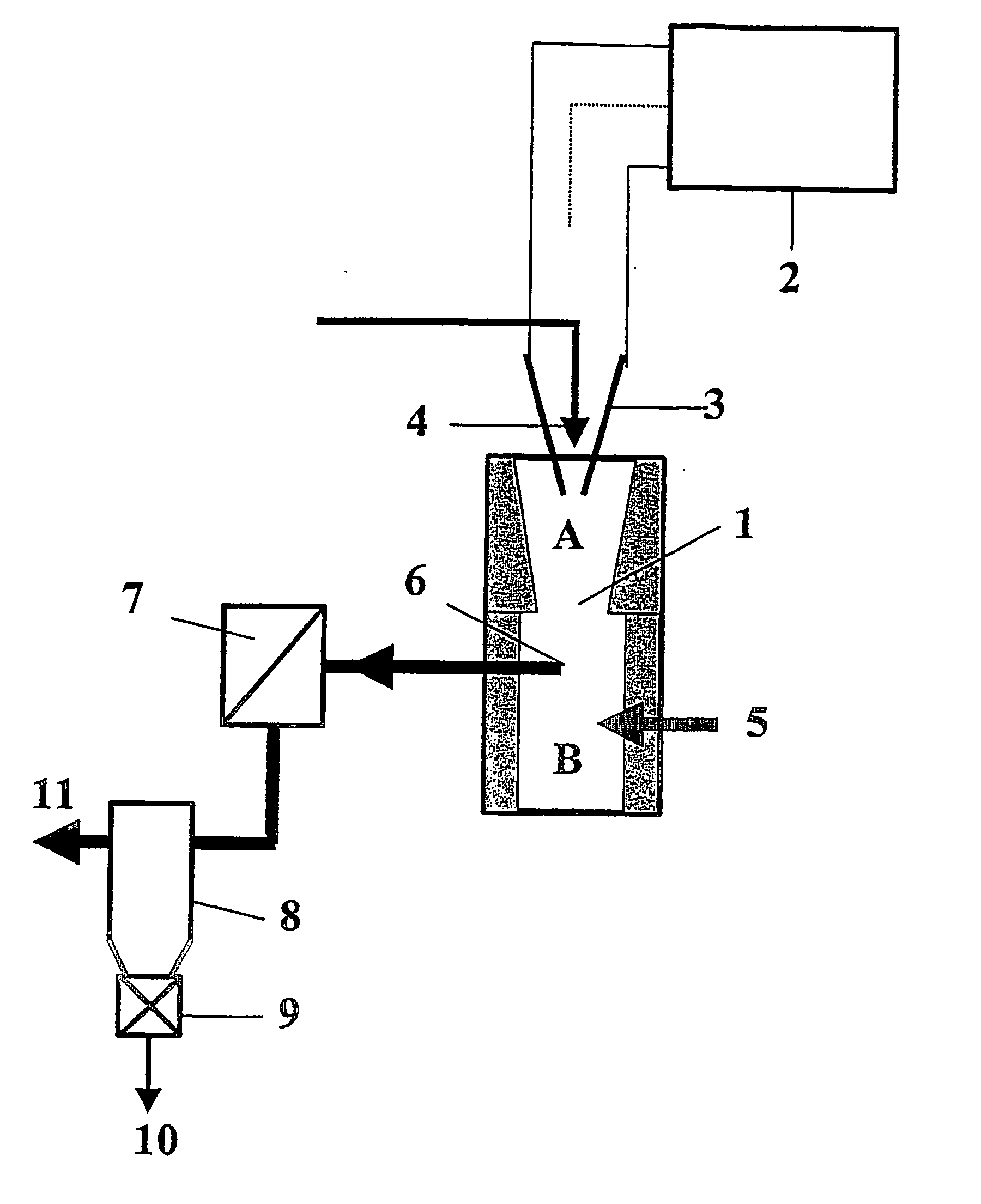
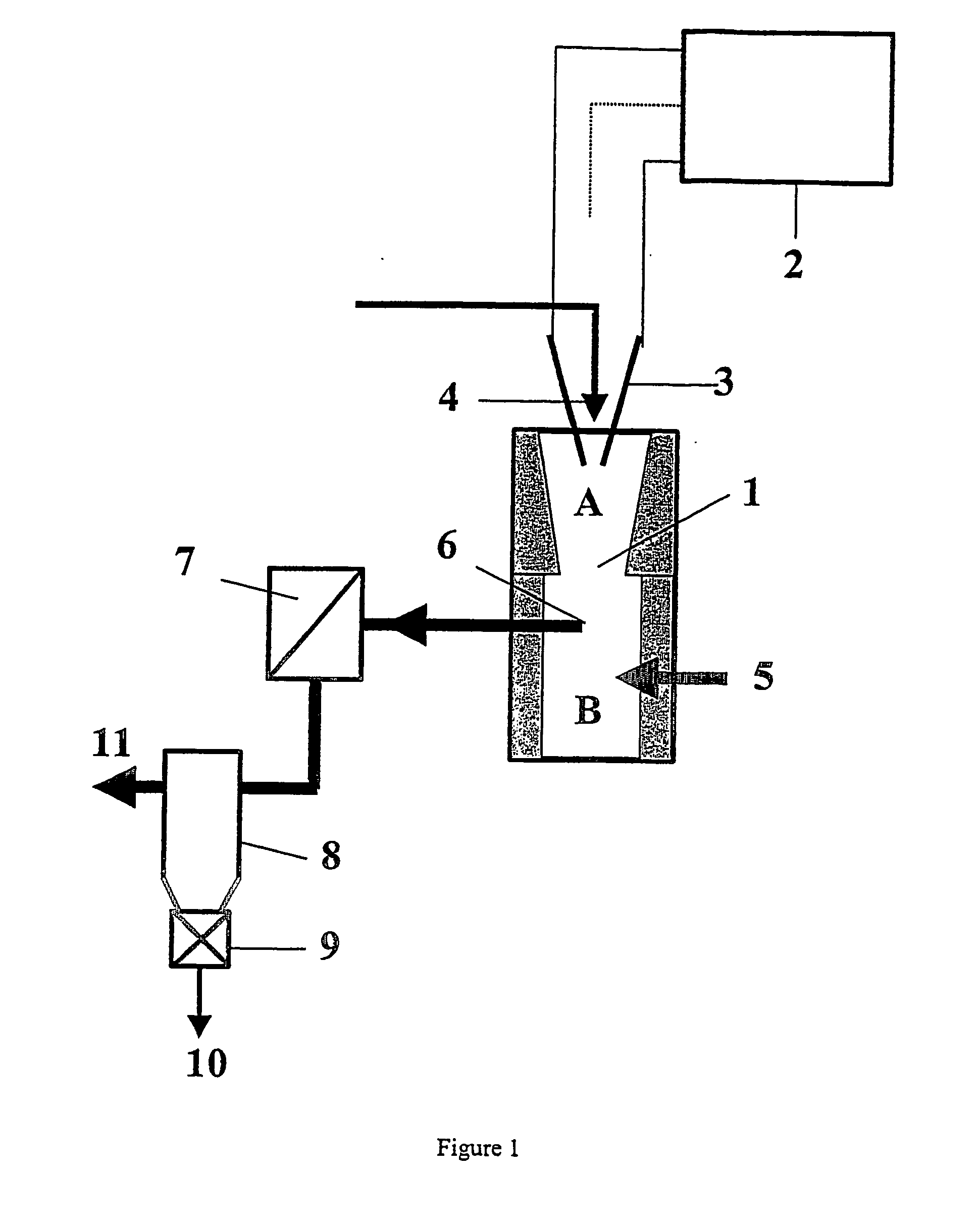
[0099] The reactor set-up, described in FIG. 1, consists of a cylindrical reactor of a height of 2 meters in stainless steel with water-cooled walls and 400 mm internal diameter. The upper part of the reactor is fitted with thermal insulation cone-shaped in graphite of 500 mm height and an internal diameter between 150 and 80 mm. Three electrodes in graphite of 17 mm diameter are positioned through the head of the reactor by a sliding device system electrically insulated. A central injector of 4 mm internal diameter allows the introduction of the precursor by means of a carrier plasma gas in the upper part of the reactor. A plasma power supply, employing a three phase electricity source up to 666 Hz with a maximum power of 263 kVA, a RMS current range of up to 600 A and a RMS voltage range of up to 500 V, was used to supply electricity to the three graphite electrodes, their tips being arranged in the shape of an inversed pyramid.

[0100] The carrier plasma gas is helium and the prec...

example 2

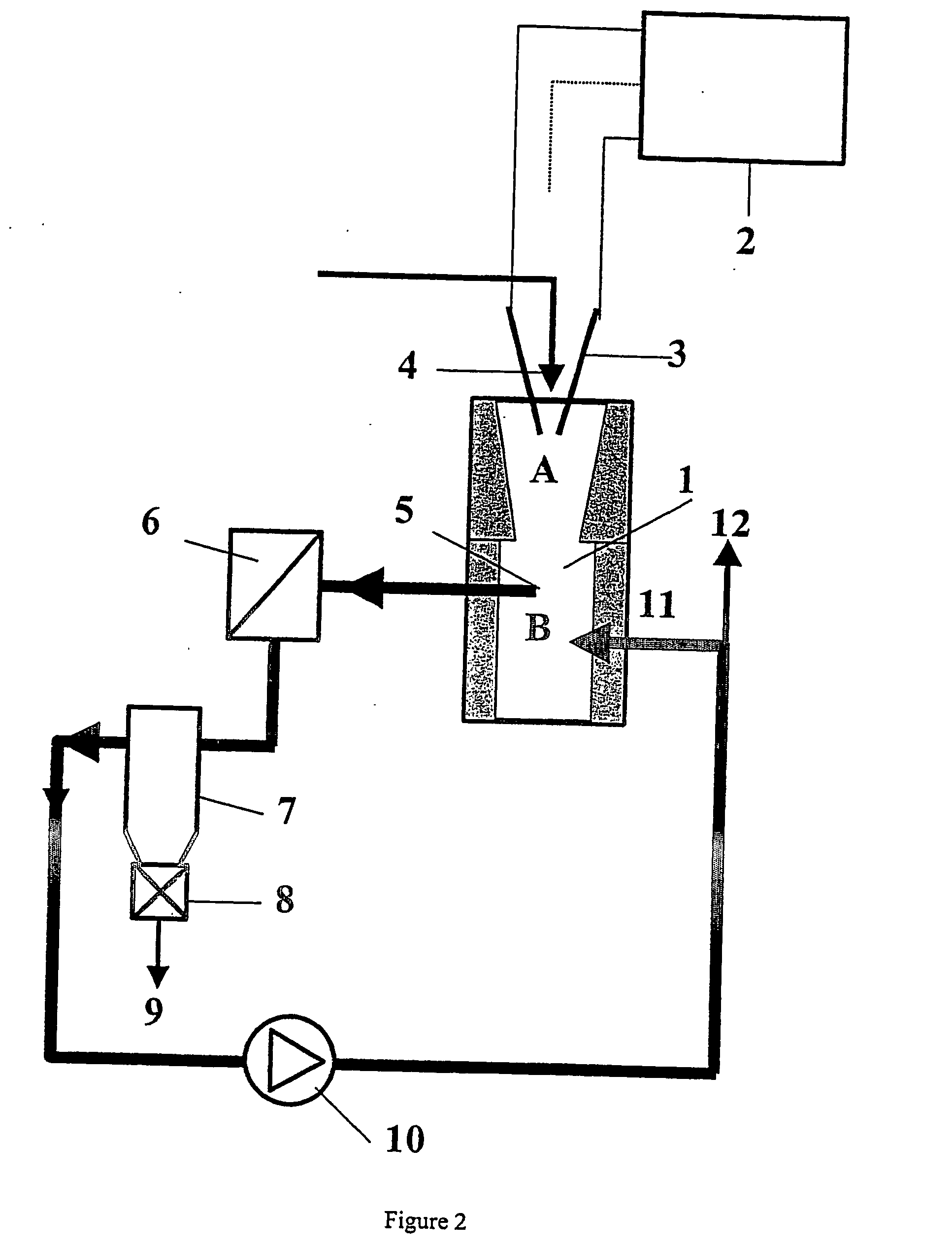
[0103] One operates in similar conditions to example 1 but according to the configuration corresponding to FIG. 2. Carrier plasma gas is nitrogen at a flow-rate of 2 Nm3 / h. The quenching gas is nitrogen at a flow-rate of 50 Nm3 / h. Electrical conditions are 350 A and 200 V. In these conditions necklace shaped carbon nanostructures are produced in very high concentration.

example 3

[0104] One operates in similar conditions to example 1 but according to the configuration corresponding to FIG. 2. Carrier plasma gas is helium at a flow rate of 3 Nm3 / h. The quenching gas is a mixture of nitrogen / helium at a flow rate of 50 Nm3 / h. Electrical conditions are those of example 1. The precursor is ethylene (C2H4) mixed with nickel-cobalt powders corresponding to a weight ratio in relation to the carbon of 3 weight % for the nickel and 2 weight % for the cobalt. The recovered product is composed of: 55 weight % of single walled carbon nanotubes, 13 weight % of carbon nanofibres and multi walled carbon nanotubes, the rest of undefined carbon nanostructures with catalyst particles.

[0105] The carbon nanostructures of FIG. 4-9 illustrate embodiments of the invention. The preferred carbon nanostructures of this invention have the structure of a linear chain of connected, substantially identical sections of beads, namely spheres or bulb-like units or trumpet shaped units, pre...


PUM

PropertyMeasurementUnit
Temperatureaaaaaaaaaa
Lengthaaaaaaaaaa

Abstract

Continuous process for the production of carbon-based nanotubes, nanofibres and nanostructures, comprising the following steps: generating a plasma with electrical energy, introducing a carbon precursor and/or one or more catalysers and/or carrier plasma gas in a reaction zone of an airtight high temperature resistant vessel optionally having a thermal insulation lining, vaporizing the carbon precursor in the reaction zone at a very high temperature, preferably 4000° C. and higher, guiding the carrier plasma gas, the carbon precursor vaporized and the catalyser through a nozzle, whose diameter is narrowing in the direction of the plasma gas flow, guiding the carrier plasma gas, the carbon precursor vaporized and the catalyses into a quenching zone for nucleation, growing and quenching operating with flow conditions generated by aerodynamic and electromagnetic forces, so that no significant recirculation of feedstocks or products from the quenching zone into the reaction zone occurs, controlling the gas temperature in the quenching zone between about 4000° C. in the upper part of this zone and about 50° C. in the lower part of this zone and controlling the quenching velocity between 103 K/s and 106 K/s quenching and extracting carbon-based nanotubes, nanofibres and other nanostructures from the quenching zone, separating carbon-based nanotubes, nanofibres and nanostructures from other reaction products.

Description

FIELD OF THE INVENTION [0001] The invention relates to a process for the economical and continuous production of carbon-based nanotubes, nanofibres and nanostructures. The invention also relates to novel carbon nanostructures. BRIEF DESCRIPTION OF THE PRIOR ART [0002] Carbon fibres have long been known and many methods for their production have been developed, see for example M. S. Dresselhaus, G. Dresselhaus, K. Suglhara; I. L. Spain, and H. A. Goldberg, Graphite Fibers and Filaments, Springer-Verlag, new York (1988). [0003] Short (micron) lengths of forms of fullerene fibres have recently been found on the end of graphite electrodes used to form a carbon arc, see T. W. Ebbesen and P. M. Ajayan, “Large Scale Synthesis of Carbon Nanotubes.” Nature Vol. 358, pp. 220-222 (1992), and M. S. Dresselhaus, “Down the Straight and Narrow,” Nature, Vol. 358, pp. 195-196, (16. Jul. 1992), and references therein. Carbon nanotubes (also referred to as carbon fibrils) are seamless tubes of graphi...

Claims


Application Information

Patent Timeline
IPC IPC(8): D01F9/12C01B31/00B01J21/18B01J19/08C01B31/02
CPCB01J19/088C01B2202/36B01J2219/00123B01J2219/0811B01J2219/0869B01J2219/0886B01J2219/0892B01J2219/0894B82Y30/00B82Y40/00C01B31/0213C01B31/0233C01B31/024C01B2202/02C01B2202/06B01J2219/00108C01B32/162C01B32/164C01B32/154
Inventor CHARLIER, JEAN-CHRISTOPHEFABRY, FREDERICFLAMANT, GILLESFULCHERI, LAURENTGONZALEZ, JOSEGRIVEI, EUSEBIUGRUENBERGER, THOMAS M.OKUNO, HANAKOPROBST, NICOLAS
Owner ТІМКАЛ SА
Why Eureka
Try Eureka