Plastics processing machine

a processing machine and plastics technology, applied in the field of plastics processing machines, can solve the problems of difficult integration of changes in the application software of peripheral devices, which are often implemented by device suppliers, and the difficulty of controlling the individual components of complex plastic processing machines such as injection molding machines in a coordinated fashion from a single operating unit. , to achieve the effect of reducing the number of operating units

Inactive Publication Date: 2007-08-09
SUMITOMO SHI DEMAG PLASTICS MACHINERY
View PDF11 Cites 13 Cited by
  • Summary
  • Abstract
  • Description
  • Claims
  • Application Information

AI Technical Summary

Benefits of technology

[0014] The screen display may include a display of actual values of the corresponding state of the subsystem and / or the machine controller, but may also display a control interface of the corresponding system. Any entry performed on the screen of the operating unit in the corresponding screen display, can according to the invention be transmitted back to the initial unit, i.e., the machine controller or the control unit, on whose screen display the entry was originally performed. The entry is further processed in the original unit as if the entry were performed directly on a screen associated with that original unit, so that the operation of the control unit as well as of the machine controller can now be performed from a single screen. This may be the screen directly associated with the control unit or the screen directly associated with the machine controller. Advantageously, the operation is hereby simplified because it can be performed from the screen of a single operating unit. Elimination of additional operating units of the subsystem or at least their screens represents additional savings in both space and cost.
[0015] Significant additional advantages are also attained by representing the actual image information of the corresponding displayed machine controller and / or the control unit and by having the option to control the same from a single screen of the at least one operating unit, in particular when integrating additional procured subsystems. The machine controller need not intervene when displaying information on and operating from an operating unit of the plastics processing machine, because the display, in particular of the user interfaces, is essentially performed in the original. This obviates the need for continuously updating the control software on the plastics processing machine, which to date had to coincide with upgrades of the control units of the added subsystems, so as to ensure full operability of the subsystems. Upgrades of the subsystems, in particular of the peripheral devices, can therefore be adopted and integrated retaining their full functionality, without requiring time-consuming and costly internal upgrades or changes in the machine controller.

Problems solved by technology

Disadvantageously, a separate control must be provided for the switches and only one data output line can be connected to the data main line at any given time.
Conventional devices have the drawback that control of the individual elements of complex plastics processing machines, such as injection molding machines, in a coordinated fashion from a single operating unit is difficult, in particular if the machines include several subsystems, for example peripheral devices.
Moreover, changes in the application software of the peripheral devices, which are frequently implemented by a device supplier, are difficult to integrate.

Method used


Image

  • Plastics processing machine
  • Plastics processing machine
  • Plastics processing machine

Examples


Embodiment Construction

[0039] Throughout all the Figures, same or corresponding elements are generally indicated by same reference numerals. These depicted embodiments are to be understood as illustrative of the invention and not as limiting in any way. It should also be understood that the drawings are not necessarily to scale and that the embodiments are sometimes illustrated by graphic symbols, phantom lines, diagrammatic representations and fragmentary views. In certain instances, details which are not necessary for an understanding of the present invention or which render other details difficult to perceive may have been omitted.

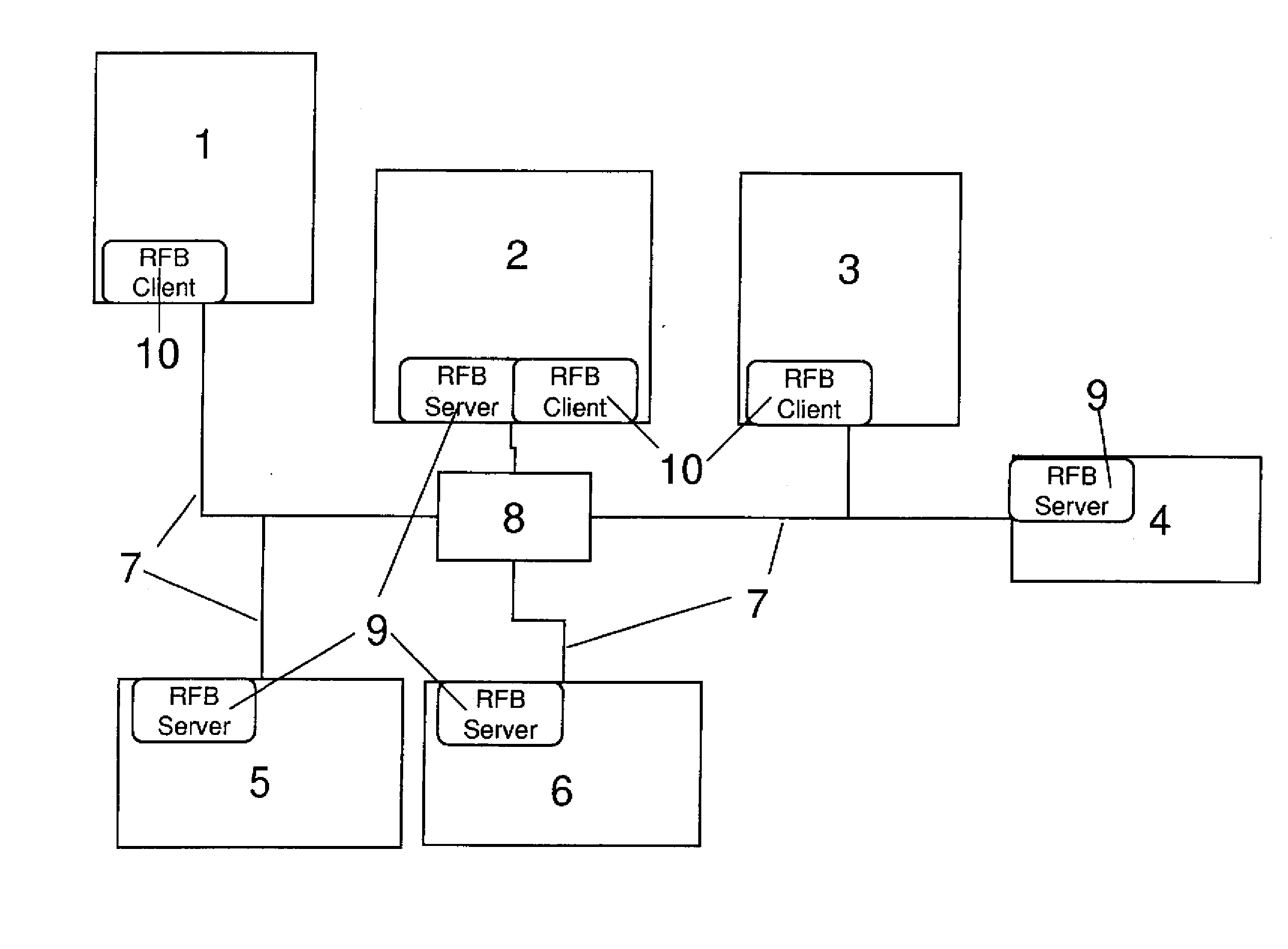
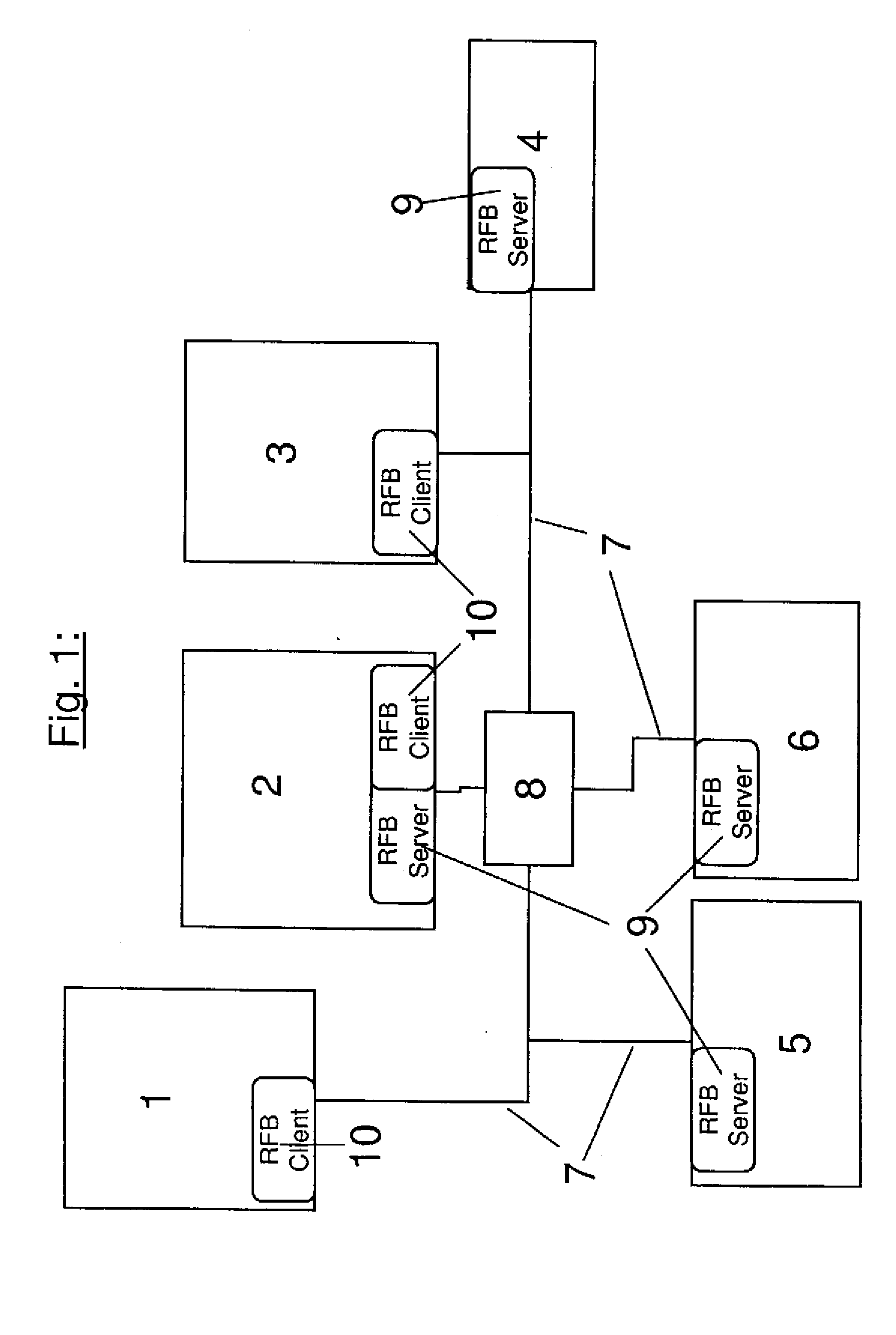
[0040] Turning now to the drawing, and in particular to FIG. 1, there is shown a schematic diagram of an injection molding machine according to the invention with operating units 2, 3, a machine controller 4, and control units of subsystems, for example a hot runner control 5 and a robot control 6 which are interconnected by suitable data lines 7 and are also connected via a...


PUM

PropertyMeasurementUnit
timeaaaaaaaaaa
data transmissionaaaaaaaaaa
areasaaaaaaaaaa

Abstract

A plastics processing machine, particularly an injection molding machine, with an operating unit, a machine controller, and a subsystem having its own dedicated control unit is described. The machine controller and control device each generate a screen display and can be operated via the screen display. The operating unit is connected or can be connected for data transmission to both the machine controller and the control unit. Both of the machine controller and the control unit can be monitored and controlled by reproducing the original screen output from the machine controller and the control unit on the display screen of the operating unit, where new information can be entered. The information entered on the display screen of the operating unit is then transmitted back to the corresponding controller or unit associated with the reproduced screen display where the information was entered.

Description

CROSS-REFERENCES TO RELATED APPLICATIONS [0001] This application is a continuation of prior filed copending PCT International application no. PCT / EP2005 / 055045, filed Oct. 6, 2005, which designated the United States and has been published but not in English as International Publication No. WO 2006 / 042788 and on which priority is claimed under 35 U.S.C. §120, and which claims the priority of German Patent Application, Serial No. 10 2004 051 106.3, filed Oct. 19, 2004, pursuant to 35 U.S.C. 119(a)-(d), the contents of which are incorporated herein by reference.BACKGROUND OF THE INVENTION [0002] The present invention relates, in general, to a plastics processing machine, and more particularly to an injection molding machine. [0003] Nothing in the following discussion of the state of the art is to be construed as an admission of prior art. [0004] WO 02 / 32649 A1 describes an injection molding apparatus, in particular for plastic materials, with at least two controllers which are connecte...

Claims


Application Information

Patent Timeline
Patent Type & Authority Applications(United States)
IPC IPC(8): G06F17/00
CPCB29C45/76G05B2219/36168B29C47/92B29C2045/7606B29C2045/7633B29C2945/76993B29C2947/92514B29C2947/92571B29C2947/92704B29C2947/9279G05B19/4185G05B19/4186G05B2219/31145G05B2219/31151G05B2219/31186G05B2219/31457G05B2219/33148G05B2219/33152B29C47/0009B29C48/92B29C2948/92704B29C48/03B29C2948/92514B29C2948/92571B29C2948/9279Y02P90/02
Inventor STANGE, BODODACHS, OSWALDMELKUS, ANDREAS
Owner SUMITOMO SHI DEMAG PLASTICS MACHINERY
Why Eureka
Try Eureka