Electric reaction technology for fuels processing

a technology of reaction technology and fuels, applied in the direction of combustible gas production, electrochemical generators, hydrocarbon oil treatment products, etc., can solve the problems of unrealized heat value of carbon combustion, high complexity and expense, and all approaches to move toward environmentally friendly fuels

Active Publication Date: 2007-08-16
EGT ENTERPRISES
View PDF22 Cites 23 Cited by
  • Summary
  • Abstract
  • Description
  • Claims
  • Application Information

AI Technical Summary

Benefits of technology

[0009]Embodiments of the invention provide a method and apparatus for producing hydrogen wherein a hydrocarbon gas is fed into an electric reaction technology system to decompose the hydrocarbon gas to hydrogen gas and carbon solids. The electric reaction technology system comprises one or more heating zones, wherein each heating zone comprises one or more heating stations and each heating station comprises one or more heating screens. Preferably, a final near-equilibrium attainment zone without additional heat input follows either the complete ERT heating phase or one or more stages of the ERT heating phase. In an illustrative embodiment of the invention, the attainment zone comprises a carbon reaction chamber. Preferably, the temperature of the hydrogen and any remaining carbon and hydrocarbons leaving the electric reaction technology system is in the range of about 2000° F. to about 2700° F. After passing the hydrogen gas through the electric reaction technology system, the hydrogen gas and any remaining carbon solids and hydrocarbon gas are cooled. The hydrogen gas and any remaining carbon solids and hydrocarbon gas then flow through a phase separation system, such as a scrubber, filtration or drying system for example, to remove substantially all of the carbon, leaving hydrogen product.

Problems solved by technology

All approaches to move toward environmentally friendly fuels entail great complexity and expense.
In such processes, the heating value of carbon combustion would be unrealized as useful heat.

Method used


Image

  • Electric reaction technology for fuels processing
  • Electric reaction technology for fuels processing
  • Electric reaction technology for fuels processing

Examples


Embodiment Construction

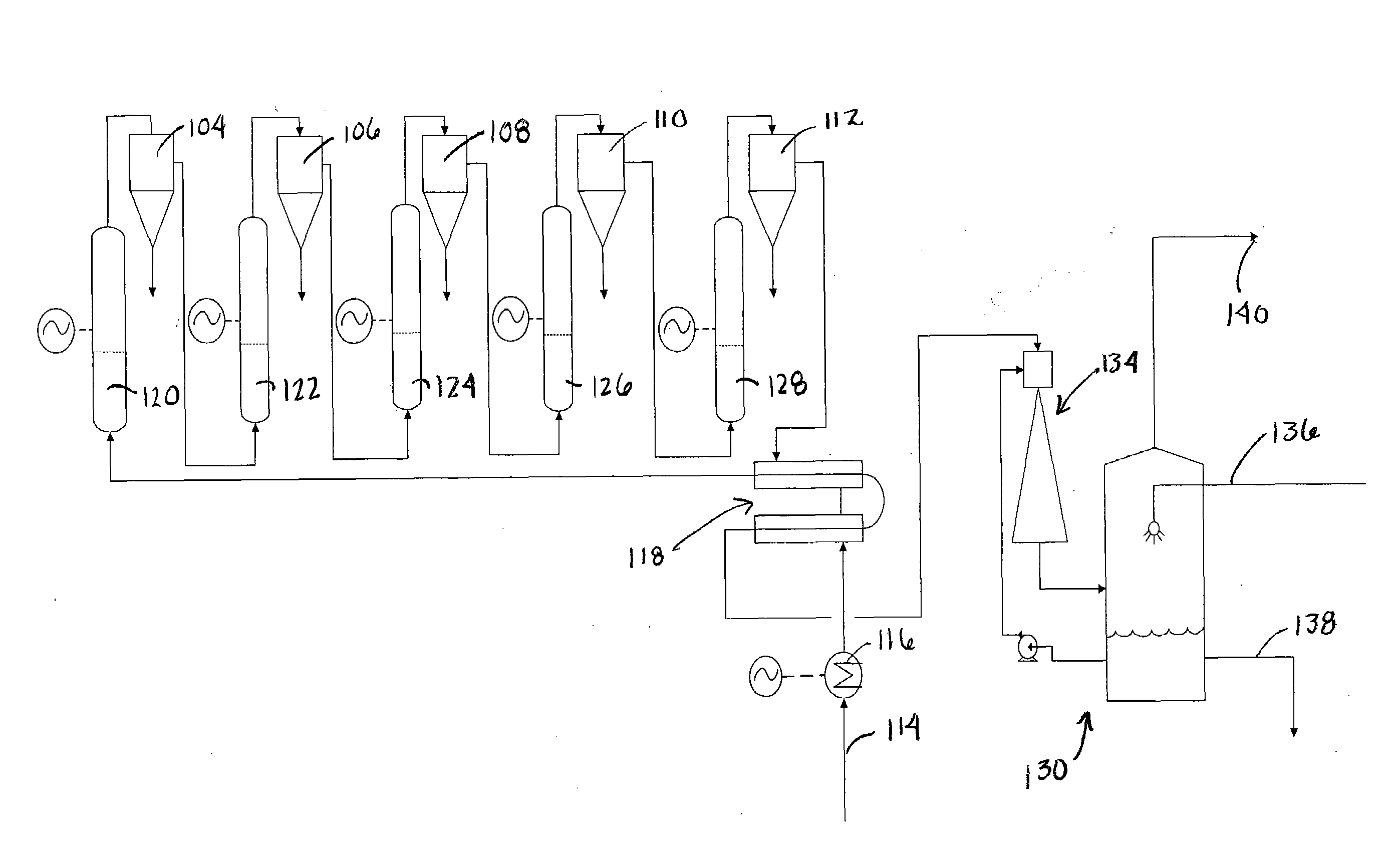
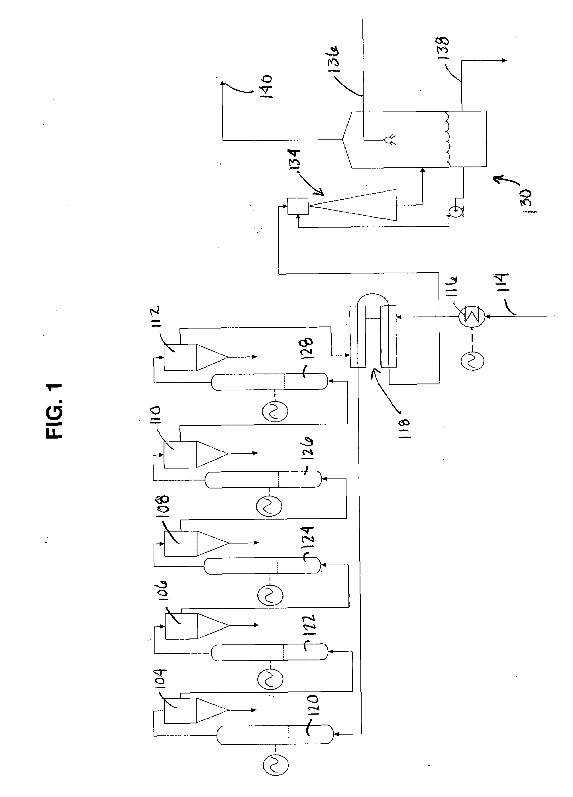
[0025]Disclosed is an Electric Reaction Technology (ERT) process and apparatus directed to the production of hydrogen and carbon solids by decomposition of methane or natural gas. The ERT apparatus may also be used for pyrolysis processes. When used for the former, the ERT process may also be called a fuel decarbonization process. The process employs electric resistance heaters capable of adaptation to the selective decomposition of hydrocarbons and filtration / separation equipment capable of effective filtration / separation under very high carbon loading.

[0026]As the source of electricity may be an environmental concern, such a plant could be situated near an economical and eco-friendly wind farm to provide the necessary electricity. There would be little or no resulting carbon dioxide or other greenhouse gas emissions from either one of these processes, as compared to conventional fossil fuel technologies.

[0027]Hydrocarbon decomposition, also known as fuels decarbonization, has been...


PUM

PropertyMeasurementUnit
temperatureaaaaaaaaaa

Abstract

A method and apparatus for producing hydrogen is disclosed wherein a hydrocarbon gas is fed into an electric reaction technology system to decompose the hydrocarbon gas to hydrogen gas and carbon solids. The electric reaction technology system comprises one or more heating zones, wherein each heating zone comprises one or more heating stations and each heating station comprises one or more heating screens followed by a final near-equilibrium attainment zone without additional heat input. After passing the hydrogen gas through the electric reaction technology system the hydrogen gas and any remaining carbon solids and hydrocarbon gas are cooled. The hydrogen gas and any remaining carbon solids and hydrocarbon gas flow through a scrubber, filter, drier or other phase separation system to remove substantially all of the carbon, leaving hydrogen product. The electric reaction technology system can also be used to pyrolyze hydrocarbons.

Description

[0001]This application is based on, and claims priority to, provisional application having Ser. No. 60 / 773,613, having a filing date of Feb. 15, 2006, entitled Electric Reaction Technology for Pollution-Free Fuels Decarbonization.BACKGROUND OF THE INVENTION[0002]Carbon dioxide is produced when burning any hydrocarbon fuel. Additional carbon dioxide is produced by the chemical industry when hydrocarbons are used as feedstocks for catalytic steam reforming, partial oxidation and water gas shift reaction processes to manufacture hydrogen-containing synthesis gas. Little has changed in the last 50 years and almost all this carbon dioxide finds its way into the atmosphere. In recent years, carbon dioxide has been identified as a contributor to global climate change. Governments and corporations have proposed many methods to reduce or manage atmospheric carbon dioxide emissions. Furthermore, major efforts have been mounted to produce hydrogen more economically, since it burns cleanly, pro...

Claims


Application Information

Patent Timeline
Patent Type & Authority Applications(United States)
IPC IPC(8): H01M8/06
CPCC01B3/24C10G2300/4081C10G9/24C10G2400/20C10G2400/24H01M8/04022H01M8/0612H01M2008/1293H01M2008/147Y02E60/50Y02E60/525Y02E60/526C10G2300/1025C10G2300/1044C10G2300/1059C10G2300/1081C01B2203/0272Y02P20/133
Inventor ENNIS, BERNARD P.
Owner EGT ENTERPRISES
Why Eureka
Try Eureka