Rotation detection device

Inactive Publication Date: 2007-08-16
TOSHIBA ELEVATOR KK
View PDF4 Cites 14 Cited by
  • Summary
  • Abstract
  • Description
  • Claims
  • Application Information

AI Technical Summary

Benefits of technology

[0049] The present invention can automatically decrease the output ripple of the rotation detection device, and thus easily reduce the torque ripple and the valocity fluctuation of an actuator such as a rotary machine in which the rotation detection device is incorporated. Further, the present invention automatically adjusts relevant parameters. Therefore, the output ripple of the rotation detecting means can be reduced easily and effectively even during the operation of the system. Furthermore, since

Problems solved by technology

The torque ripple may cause velocity fluctuation or positioning error of a servomotor.
Therefore, it may decrease machining accuracy of an NC machine, or vibrate a cage of an elevator to disturb the comfort of passengers, for example.
The torque ripple caused by the former is attributable to insufficient machining accuracy of a stator or a rotor of the motor, eccentricity of a rotor bearing, harmonic components of a magnetic field in the motor, or insufficient assembling accuracy of the transmission.
Consequently, the angular velocity feedback gain for controlling th

Method used


Image

  • Rotation detection device
  • Rotation detection device
  • Rotation detection device

Examples


Embodiment Construction

[0065] Embodiments of the present invention will now be described in detail with reference to the accompanying drawings.

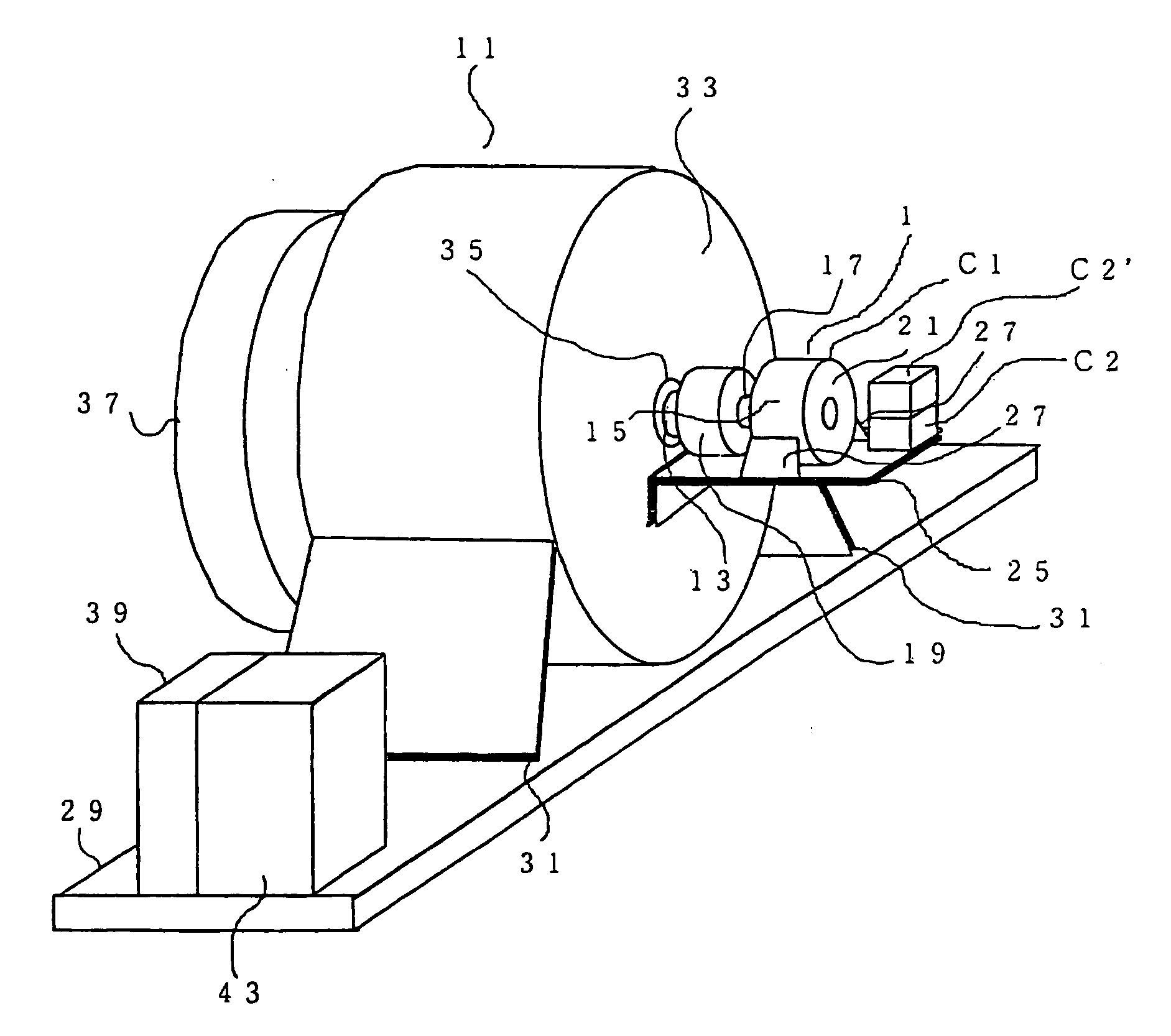
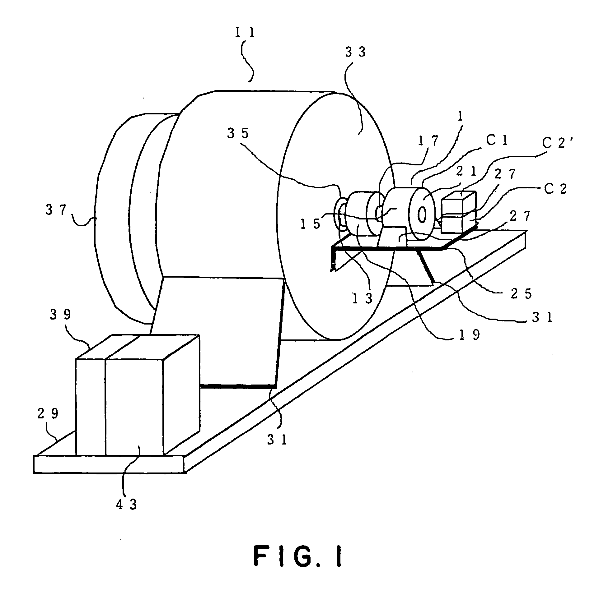
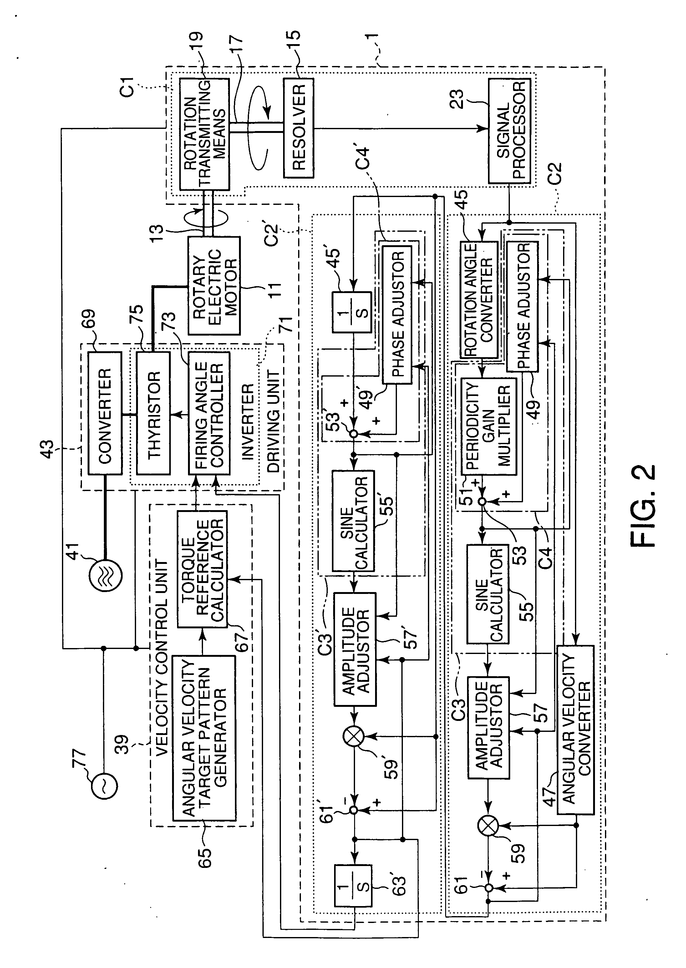
[0066] In FIGS. 1 to 4, the reference numeral 1 denotes a rotation detection device according to a first embodiment of the present invention. The rotation detection device 1 includes rotation detecting means C1 and rotation calculating means C2, C2′.

[0067] The rotation detecting means Cl includes a resolver 15, an input rotary shaft 17, and rotation transmitting means 19. The resolver 15 is mounted on a rotary electric motor 11, which is a detection object, and outputs a voltage that is proportional to the rotation angle of a rotor rotary shaft 13 of the rotary electric motor 11. The input rotary shaft 17 is directly coupled to rotor (not shown) of the resolver 15. The rotation transmitting means 19 transmits the rotation of the rotor rotary shaft 13 to the input rotary shaft 17.

[0068] The rotation transmitting means 19, which is connected to one end of the roto...


PUM


Abstract

Torque ripple of a motor due to a rotation detection device is reduced. A periodicity gain multiplier 51 multiplies the rotation angle θ of a detection target by a ripple periodic number m per rotation of the detection target. An adder 53 adds a phase adjusting value “ψ” from a phase adjustor 49 to the value “mθ”. The value “sin(mθ+ψ)”, which is calculated by a sine calculator 55, is multiplied by a predetermined gain G by an amplitude adjustor 57 and by the angular velocity ω of the detection target by a multiplier 59. A subtractor 61 subtracts the output of the multiplier 59 from the value “ω” and outputs “ω(1Gsin(mθ+ψ))”. The output of the subtractor 61 and the output “mθ+ψ” of the adder 53 are input to the phase adjustor 49 and amplitude adjustor 57. The phase adjustor 49 calculates the phase adjusting value “ψ” based on the summation of the derivative values of the outputs from the subtractor 61sampled for each “π/2” of the output from the adder 53. The amplitude adjustor 57 calculates the gain G based on the summation of the differences between averages of the sampled values at “0” and “π” of the output of the adder 53 and averages of the time integration value at the integral interval of “0” to “π”.

Description

TECHNICAL FIELD [0001] The present invention relates to a rotation detection device that detects rotary motion of a rotary machine and is incorporated in a control system for controlling the operation of the rotary machine based on the detection results of the rotation detection device. More particularly, the present invention relates to a technology for reducing the torque ripple of the rotary machine by reducing a ripple component contained in an output signal of the rotation detection device. Background Art [0002] In general, a motor has a torque ripple. The torque ripple may cause velocity fluctuation or positioning error of a servomotor. Therefore, it may decrease machining accuracy of an NC machine, or vibrate a cage of an elevator to disturb the comfort of passengers, for example. The torque ripple may be caused by a motor itself (containing a transmission), or by a rotation detection sensor (i.e., rotation detection device) of the motor. The torque ripple caused by the forme...

Claims


Application Information

Patent Timeline
IPC IPC(8): G01L3/00G01D5/244G01D5/245G01P3/46H02P7/00H02P29/00
CPCG01P3/46
Inventor MORISHITA, MIMPEI
Owner TOSHIBA ELEVATOR KK
Why Eureka
Try Eureka