Cooling tower with direct and indirect cooling sections

a technology of cooling tower and cooling section, which is applied in the direction of combustion air/fuel air treatment, machines/engines, combustion gas purification/modification, etc., can solve the problems of limited application and utility limited maximum wet mode performance of coil or indirect section, and low cooling capacity of coil shed when operated

Active Publication Date: 2007-08-16
BALTIMORE AIRCOIL CO INC
View PDF13 Cites 39 Cited by
  • Summary
  • Abstract
  • Description
  • Claims
  • Application Information

AI Technical Summary

Benefits of technology

[0006] In one embodiment, the present invention provides a mechanical draft cooling tower comprising an air inlet and an air outlet. A liquid spray assembly adapted to spray liquid downwardly between the air inlet and the air outlet is provided. A fill sheet assembly is mounted beneath the liquid spray assembly to provide direct cooling of the liquid spray flowing downwardly onto the fill sheet assembly.

Problems solved by technology

Such coil sheds have little to no cooling capacity when operated without the spray water flowing downwardly over the direct cooling or fill section.
Such limitation on the operation of the tower limits the application and utility for such towers as they typically cannot be operated dry as during the winter months in cold climates.
Further, the maximum wet mode performance of the coil or indirect section is limited as no air enters this section of the cooling tower.

Method used


Image

  • Cooling tower with direct and indirect cooling sections
  • Cooling tower with direct and indirect cooling sections
  • Cooling tower with direct and indirect cooling sections

Examples


Embodiment Construction

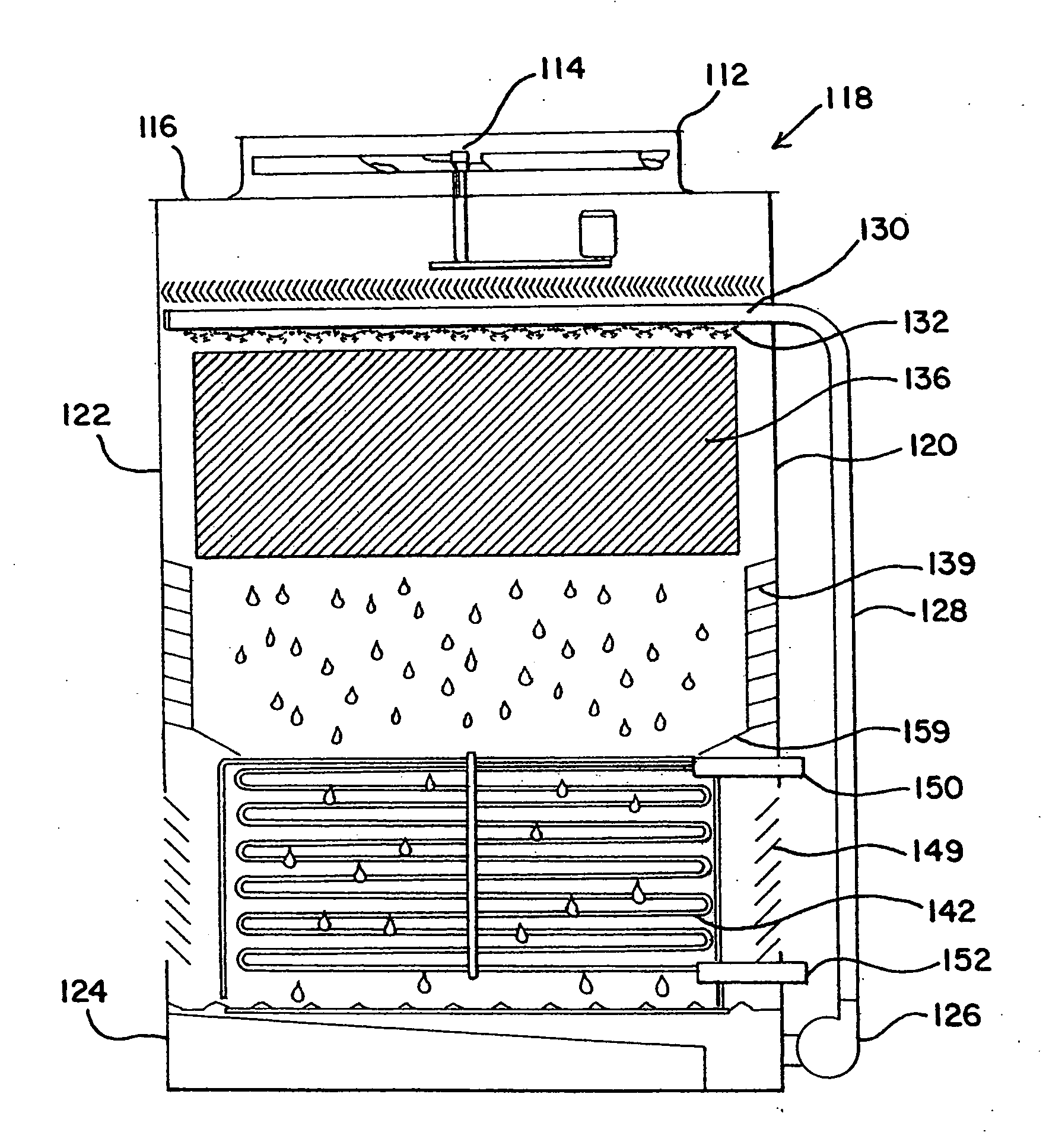
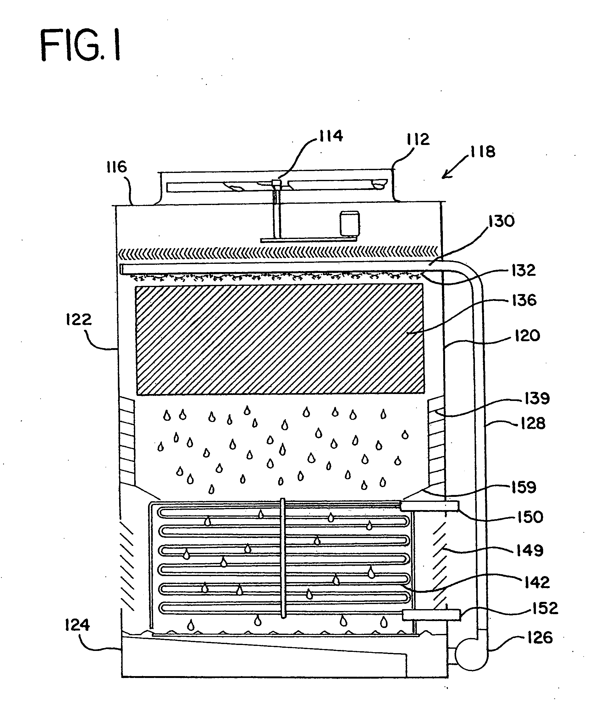
[0013] Referring now to FIG. 1 of the drawings, a cooling tower is shown generally at 118 and comprises an outlet fan enclosure 112 housing a fan 114 therein. Cooling tower 118 is of a generally rectangular or square shape, comprising an upper surface 116, and end walls 120 and 122. Fan 114 induces a draft upwardly and out of outlet fan enclosure 112, with air being drawn inwardly from cooling tower louver fill section opening 139 and indirect inlet section 149.

[0014] Cooling water is collected in collection sump 124 and is pumped upwardly via pump 126 and piping 128. Such cooling water then enters distribution pipe 130, spraying downwardly out of spray nozzles 132 onto fill section or direct cooling section 136. Fill section 136 comprises a plurality of plastic sheets that are stacked or hung within the direct cooling section of cooling tower 118. Typically such sheets are comprised of plastic material such as polyvinyl chloride or polypropylene, having a generally wavy or grooved...


PUM

PropertyMeasurementUnit
gravityaaaaaaaaaa
surface areaaaaaaaaaaa
cooling capacityaaaaaaaaaa

Abstract

A mechanical draft cooling tower includes an air inlet and an air outlet. A liquid spray assembly is provided below the air outlet. A fill shell assembly is provided below the liquid spray assembly such that liquid can be sprayed onto the fill sheet assembly. An indirect heat exchange assembly is mounted beneath the fill sheet assembly. The indirect assembly usually comprises a series of coils through which a fluid to be cooled is circulated. A first air inlet is provided beneath the fill sheet assembly and includes a closing assembly. A second air inlet is provided beneath a top surface of the indirect assembly and includes a closing assembly.

Description

BACKGROUND OF INVENTION [0001] The present invention relates generally to cooling towers, and more specifically, to an evaporative heat and mass exchanger with a coil module for evaporative closed circuit cooling or evaporative condensing. [0002] In an induced draft cross flow or counter flow cooling tower, a fan is mounted in the roof outlet of the tower. This fan draws or induces airflow inwardly into the cooling tower through a side wall or opposite side walls of the tower. Water or other evaporative liquid to be cooled is pumped to the top of the cooling tower structure and distributed through a series of spray nozzles. These spray nozzles emit a diffuse spray of water across the top of a fill media. Such fill media typically comprises a bundle of spaced parallel plastic sheets across each of which the water spray is dispersed and downwardly passed by gravity. The large surface area across which the water is dispersed on such sheets leads to cooling by the induced air flow direc...

Claims


Application Information

Patent Timeline
Patent Type & Authority Applications(United States)
IPC IPC(8): B01F3/04
CPCF28C1/14Y10T29/4935Y10S261/11F28F25/12Y02B30/70
Inventor FACIUS, TIMOTHY P.MORRISON, FRANK T.
Owner BALTIMORE AIRCOIL CO INC
Why Eureka
Try Eureka