Heat removal and recovery in biomass pyrolysis

a biomass pyrolysis and biomass technology, applied in the direction of charge manipulation, furnaces, combustion types, etc., can solve the problems of increasing solid particle entrainment and loss, not being applicable to all pyrolysis systems in terms of meeting cost and performance objectives, etc., to reduce the overall the effect of increasing operational flexibility and reducing the temperature of the reheater

Active Publication Date: 2016-09-13
ENSYN RENEWABLES
View PDF495 Cites 4 Cited by
  • Summary
  • Abstract
  • Description
  • Claims
  • Application Information

AI Technical Summary

Benefits of technology

[0008]A quench medium may be sprayed, for example, on the top of a heat carrier such as sand, residing in the reheater as a fluidized particle bed. Heat is thereby removed, for example, by conversion of water, as a quench medium, to steam. The consumption of heat advantageously reduces the overall temperature of the reheater and / or allows the pyrolysis unit to operate at a target capacity. Distributors may be located in various positions to introduce the quench medium at multiple points, for example within the dense phase bed and / or in the dilute phase, above the dense phase. Dilute phase introduction of the quench medium helps prevent dense phase bed disruptions due to sudden volume expansion (e.g., of water upon being converted to steam) in the presence of a relatively high density of solid particles. Such disruptions may detrimentally lead to increased solid particle entrainment and losses. Dense phase introduction (e.g., directly into a middle section of the dense phase bed), on the other hand, provides direct cooling of the solid particles. Such cooling is effective if introduction is carried out with sufficient control, and at a quench medium flow rate, that avoids significant disruptions of the dense phase bed. In some cases, quench medium may be introduced both into, and above, the dense phase bed, and even at multiple locations within and above the bed.

Problems solved by technology

While some heat removal schemes, such as passing the recycled heat carrier (e.g., sand) through a cooler, may be effective in certain circumstances, they may not be applicable to all pyrolysis systems in terms of meeting cost and performance objectives.
Such disruptions may detrimentally lead to increased solid particle entrainment and losses.

Method used


Image

  • Heat removal and recovery in biomass pyrolysis
  • Heat removal and recovery in biomass pyrolysis
  • Heat removal and recovery in biomass pyrolysis

Examples


Embodiment Construction

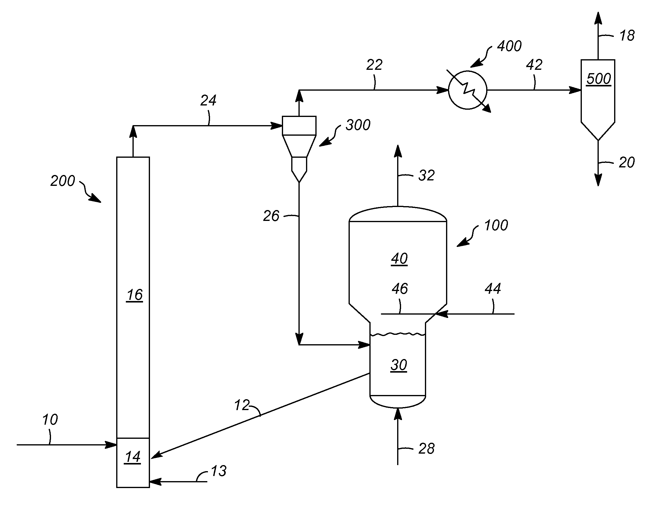
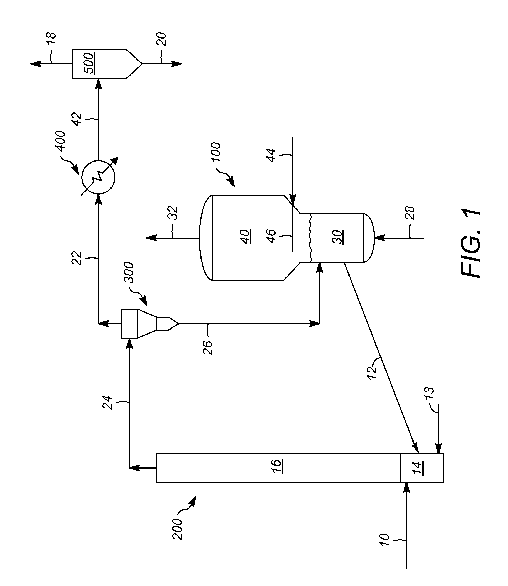
[0016]According to representative embodiments of the invention, the biomass subjected to pyrolysis in an oxygen depleted environment, for example using Rapid Thermal Processing (RTP), can be any plant material, or mixture of plant materials, including a hardwood (e.g., whitewood), a softwood, or a hardwood or softwood bark. Energy crops, or otherwise agricultural residues (e.g., logging residues) or other types of plant wastes or plant-derived wastes, may also be used as plant materials. Specific exemplary plant materials include corn fiber, corn stover, and sugar cane bagasse, in addition to “on-purpose” energy crops such as switchgrass, miscanthus, and algae. Short rotation forestry products, as energy crops, include alder, ash, southern beech, birch, eucalyptus, poplar, willow, paper mulberry, Australian blackwood, sycamore, and varieties of paulownia elongate. Other examples of suitable biomass include organic waste materials, such as waste paper and construction, demolition, an...


PUM

PropertyMeasurementUnit
temperatureaaaaaaaaaa
residence timeaaaaaaaaaa
particle sizesaaaaaaaaaa

Abstract

Pyrolysis methods and apparatuses that allow effective heat removal, for example when necessary to achieve a desired throughput or process a desired type of biomass, are disclosed. According to representative methods, the use of a quench medium (e.g., water), either as a primary or a secondary type of heat removal, allows greater control of process temperatures, particularly in the reheater where char, as a solid byproduct of pyrolysis, is combusted. Quench medium may be distributed to one or more locations within the reheater vessel, such as above and / or within a dense phase bed of fluidized particles of a solid heat carrier (e.g., sand) to better control heat removal.

Description

FIELD OF THE INVENTION[0001]The present invention relates to pyrolysis methods and apparatuses in which a solid heat carrier (e.g., sand) is separated from the pyrolysis reactor effluent and cooled with a quench medium (e.g., water) to improve temperature control. Cooling with quench medium may occur in or above a fluidized bed of the heat carrier, in which solid char byproduct is combusted to provide some or all of the heat needed to drive the pyrolysis.DESCRIPTION OF RELATED ART[0002]Environmental concerns over fossil fuel greenhouse gas emissions have led to an increasing emphasis on renewable energy sources. Wood and other forms of biomass including agricultural and forestry residues are examples of some of the main types of renewable feedstocks being considered for the production of liquid fuels. Energy from biomass based on energy crops such as short rotation forestry, for example, can contribute significantly towards the objectives of the Kyoto Agreement in reducing greenhous...

Claims


Application Information

Patent Timeline
Patent Type & Authority Patents(United States)
IPC IPC(8): F27D3/00F27D17/00F23G5/027F23G5/30F23G7/10C10G1/02F27B15/02F23B70/00C10G3/00
CPCF27B15/02C10G1/02C10G3/40C10G3/60F23G5/0276F23G5/30F23G7/10F27D17/004C10G2300/1011C10G2300/1014C10G2300/4006C10G2400/20F23G2201/304Y02P30/20Y02E50/10C10B53/02C10B49/10C10B39/06C10G3/42C10G3/50C10G2300/202
Inventor KULPRATHIPANJA, SATHITPALMAS, PAOLOMYERS, DANIEL N
Owner ENSYN RENEWABLES
Why Eureka
Try Eureka