Eureka AIR delivers breakthrough ideas for toughest innovation challenges, trusted by R&D personnel around the world.

Metal powder production apparatus and metal powder

Active Publication Date: 2007-08-16
SEIKO EPSON CORP
View PDF4 Cites 3 Cited by
  • Summary
  • Abstract
  • Description
  • Claims
  • Application Information

AI Technical Summary

Benefits of technology

[0132]The tubular member 10 illustrated in FIG. 5 has a plurality of raised portions (protrusions) 14 arranged along the circumferential direction of the bottom end surface of the tubular member 10 at substantially equal intervals. This allows the raised portions 14 to function as a split means that substantially uniformly splits the molten metal Q, which has passed the bore of the tubular member 10, in a circumferential direction of the tubular member 10 (in a divergent manner). This provides the same advantageous effects as offered by the protrusion 13 set forth above.
[0133]By forming the raised portions 14 in plural numbers along the circumferential direction of the bottom end surface of the tubular member 10, it becomes easy to form the liquid droplets Q1 along the circumferential direction of the bottom end surface (bottom end portion) of the tubular member 10 at substantially equal intervals with no likelihood of the liquid droplets Q1 being concentrated on a local area of the bottom end surface, even if the axis of the tubular member 10 remains slightly inclined with respect to a vertical direction for example. This allows the liquid droplets Q1 to uniformly fall down over the entirety of the first flow path 31.
[0134]Other examples of the split means include slots or projections formed on the inner circumferential surface of the tubular member 10 in parallel with the axis thereof. The split means of this construction can provide the advantageous effects described above.
[0135]The tubular member 10 may be made of any material insofar as it exhibits a heat resistance great enough not to suffer from degeneration or degradation when contacted with the molten metal Q. Examples of a constituent material of the tubular member 10 include various ceramics materials such as alumina and zirconia and various heat-resistant metallic materials such as tungsten.
[0136]Among them, the ceramics materials are especially preferable for use as a constituent material of the tubular member 10. The reason is that the ceramics materials are particularly high in heat resistance and less likely to undergo chemical changes such as oxidation. Furthermore, the ceramics materials show a relatively high thermal insulation property (a relatively low heat conductivity), which provides an advantage of suppressing the temperature reduction of the molten metal Q.
[0137]In the present embodiment, an instance where the water S is used as the fluid has been described representatively. The fluid may be any type of liquid or gas coolant but it is preferred to use a liquid fluid as in the present embodiment. The liquid fluid has a specific gravity and a heat capacity greater than those of the gas fluid and is therefore capable of making the molten metal Q finer and efficiently cooling the same within a short period of time when contacted with the molten metal Q (in the secondary breakup process).

Problems solved by technology

This poses a problem in that the molten bath is changed in its dispersion, cooling and solidification conditions, thus giving rise to a variation in grain diameter or particle size distribution of the metal powder produced.
Upon making contact with the air, however, the molten bath may be solidified by temperature reduction or may be degenerated or degraded by oxidation, thus leaving a possibility that the resultant metal powder shows reduction in quality.
In particular, this problem becomes conspicuous in the case where the molten metal contains highly active metal elements such as Ti and Al.
These elements are highly active and it is a conventional knowledge that the molten metal containing these elements has a difficulty in pulverization because of its tendency to be easily oxidized into an oxide film through short contact with the air.

Method used


Image

  • Metal powder production apparatus and metal  powder
  • Metal powder production apparatus and metal  powder
  • Metal powder production apparatus and metal  powder

Examples


first embodiment

[0065]First of all, description will be made on a metal powder production apparatus in accordance with a first embodiment of the present invention.

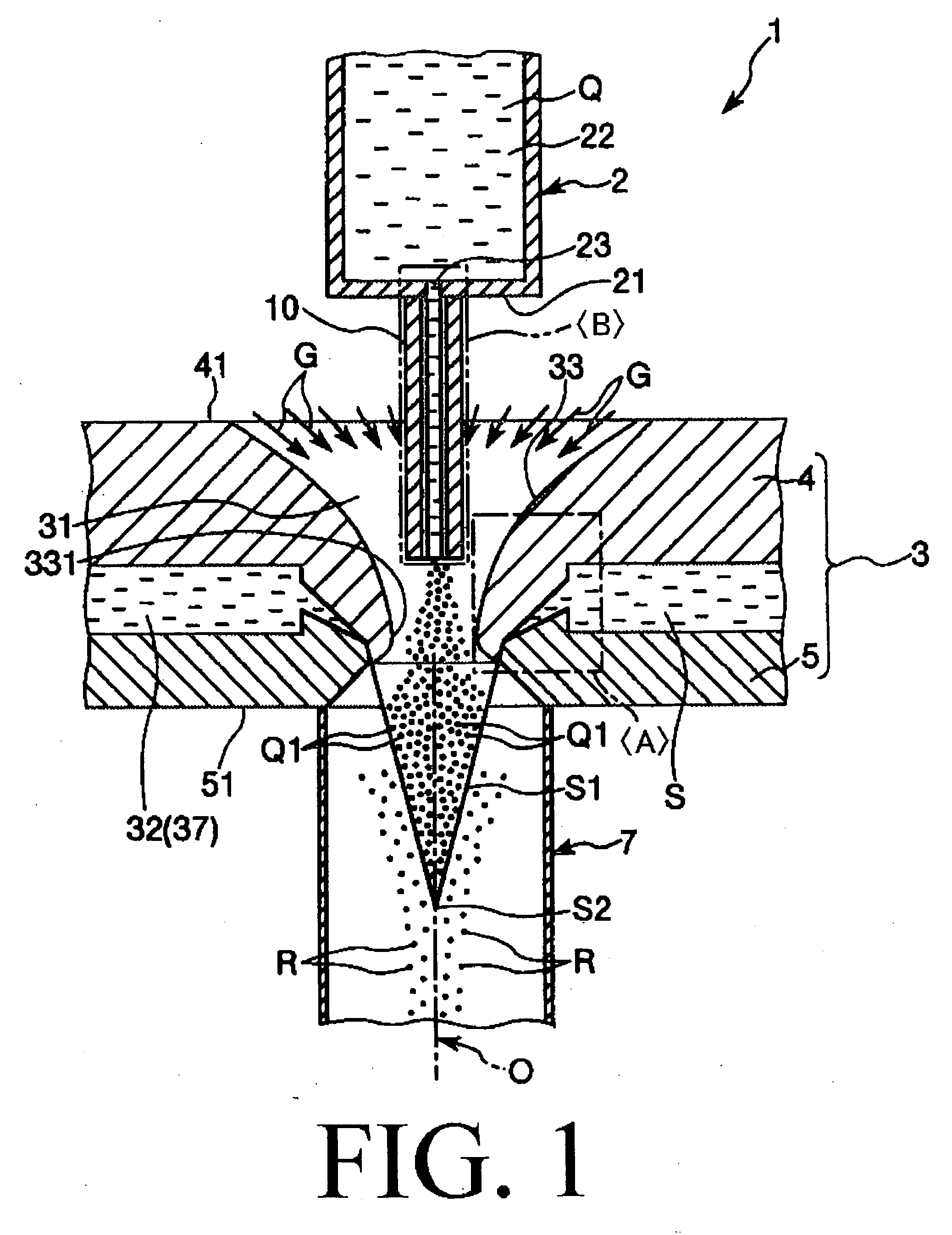
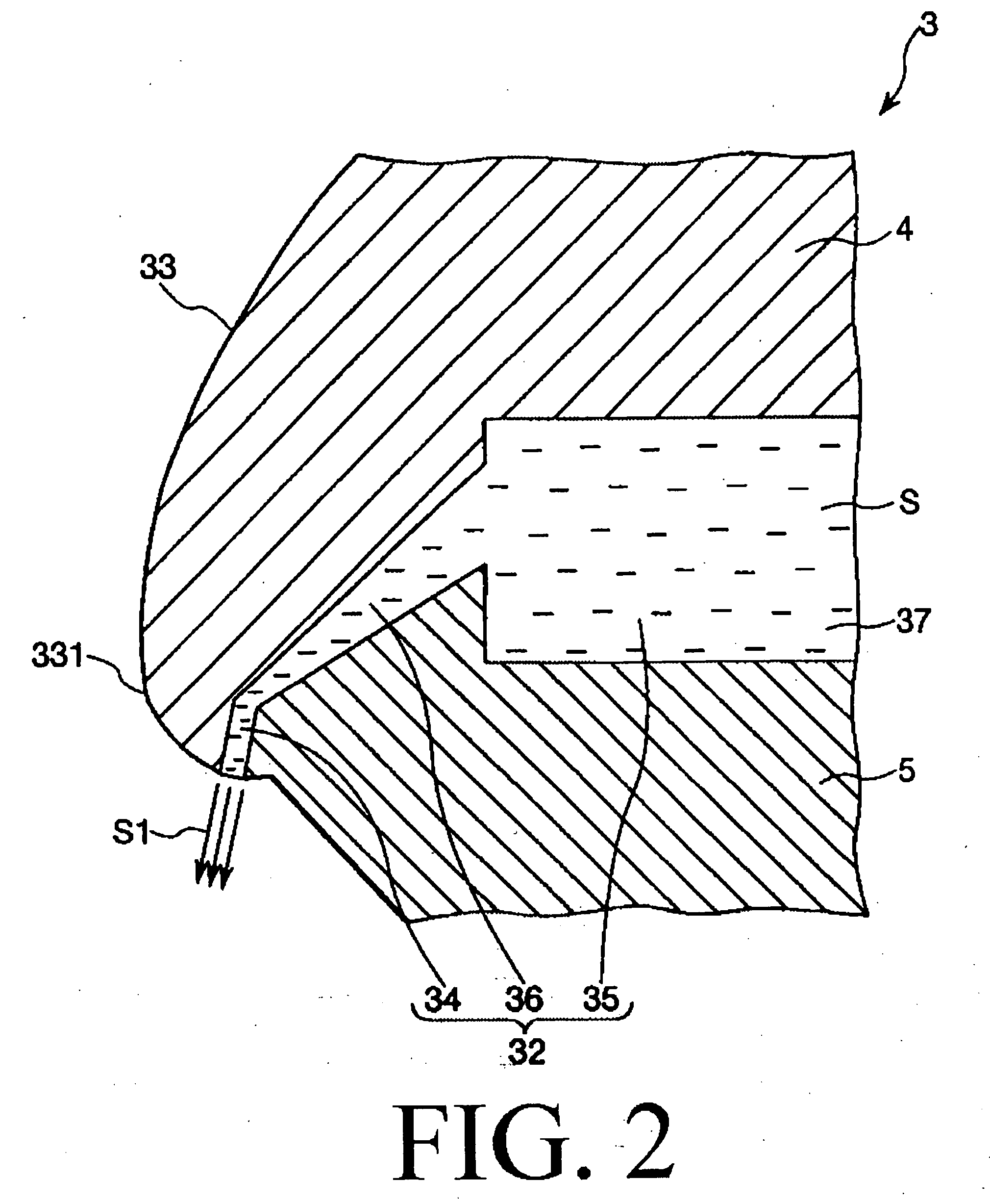
[0066]FIG. 1 is a schematic view (vertical sectional view) showing a metal powder production apparatus in accordance with a first embodiment of the present invention, FIG. 2 is an enlarged detail view (schematic view) of a region enclosed by a single-dotted chain line in FIG. 1, and FIG. 3 is an enlarged detail view (schematic view) of a region enclosed by a double-dotted chain line in FIG. 1.

[0067]In the following description, the upper side in FIGS. 1 to 3 will be referred to as “top” or “upper” and the lower side will be referred to as “bottom” or “lower”, only for the sake of better understanding.

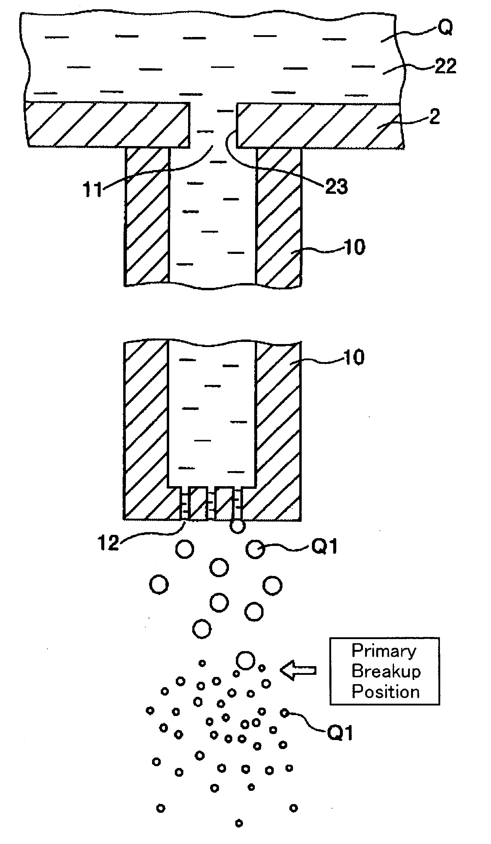
[0068]The metal powder production apparatus (atomizer) 1 shown in FIG. 1 is an apparatus that makes use of an atomizing method to pulverize molten metal Q into metal powder R. The metal powder production apparatus 1 includes a supply part (...

second embodiment

[0143]Next, description will be made on a metal powder production apparatus in accordance with a second embodiment of the present invention.

[0144]FIG. 6 is an enlarged detail view (schematic view) showing some parts of the metal powder production apparatus in accordance with the second embodiment of the present invention. In the following description, the upper side in FIG. 6 will be referred to as “top” or “upper” and the lower side will be referred to as “bottom” or “lower”, only for the sake of better understanding.

[0145]The following description of the second embodiment will be centered on the points differing from the first embodiment, with the same points omitted from description.

[0146]The metal powder production apparatus 1 of the present embodiment is the same as that of the first embodiment, except that the tubular member has a differing configuration.

[0147]As shown in FIG. 6, a plurality of tubular members 10′ are provided in the present embodiment. Just like the first emb...

third embodiment

[0150]Next, description will be made on a metal powder production apparatus in accordance with a third embodiment of the present invention.

[0151]FIG. 7 is an enlarged detail view (schematic view) showing some parts of the metal powder production apparatus in accordance with the third embodiment of the present invention. In the following description, the upper side in FIG. 7 will be referred to as “top” or “upper” and the lower side will be referred to as “bottom” or “lower”, only for the sake of better understanding.

[0152]The following description of the third embodiment will be centered on the points differing from the first embodiment, with the same points omitted from description.

[0153]The metal powder production apparatus 1 of the present embodiment is the same as that of the first embodiment, except for differences in the configuration of the first member and the second member.

[0154]As can be seen in FIG. 7, a first recess portion 43 and a first easy-to-deform portion 44 are fo...


PUM

PropertyMeasurementUnit
Areaaaaaaaaaaa
Particle sizeaaaaaaaaaa
Diameteraaaaaaaaaa

Abstract

A metal powder production apparatus is capable of efficiently producing fine metal powder with a uniform particle size. The metal powder produced by the apparatus has an increased quality. The apparatus (atomizer) makes use of an atomizing method to pulverize molten metal into metal powder. The apparatus includes a supply part (tundish) for supplying the molten metal, a nozzle provided below the supply part, a tubular member provided between the supply part and the nozzle. The tubular member is constructed to ensure that the molten metal ejected from an ejection port passes through a bore of the tubular member and then makes contact with a fluid jet. Further, the tubular member has a top end air-tightly connected to the supply part and a bottom end lying around the midway of a first flow path through which the molten metal passes.

Description

CROSS-REFERENCE TO RELATED APPLICATION[0001]This application claims priorities to Japanese Patent Applications No. 2006-039903 filed on Feb. 16, 2006 and No. 2006-331201 filed on Dec. 7, 2006 which are hereby expressly incorporated by reference herein in their entireties.BACKGROUND[0002]1. Technical Field[0003]The present invention relates to a metal powder production apparatus and metal powder.[0004]2. Related Art[0005]Conventionally, a metal powder production apparatus (atomizer) that pulverizes molten metal into metal powder by an atomizing method has been used in producing metal powder. Examples of the metal powder production apparatus known in the art include a molten metal atomizing and pulverizing apparatus disclosed in JP-B-3-55522.[0006]The molten metal atomizing and pulverizing apparatus is provided with an ejection port from which molten bath (molten metal) is ejected in a downward direction and a nozzle having a flow path through which the molten bath ejected from the ej...

Claims


Application Information

Patent Timeline
IPC IPC(8): C21C1/00
CPCB22F9/082B22F2998/00B22F9/002
Inventor SHIMURA, TOKIHIRO
Owner SEIKO EPSON CORP
Why Eureka
Eureka Blog
Learn More