
Light diffusing body and a transmission type screen

a transmission type and light diffusing technology, applied in non-linear optics, instruments, transportation and packaging, etc., can solve the problem of image appearance as colored, achieve the effect of reducing the shift of the wavelength of scattering light, high cost, and same scattering efficiency

Active Publication Date: 2007-08-16
KIMOTO CO LTD
View PDF23 Cites 19 Cited by
  • Summary
  • Abstract
  • Description
  • Claims
  • Application Information

AI Technical Summary

Benefits of technology

[0016]The principle with which the light diffusing body of the present invention can reduce the shift of the wavelength of a scattering light will be explained below.
[0017]The methods used for scattering light include the external scattering, in which light is scattered by fine convexoconcaves on the surface, and the internal scattering, in which a light is scattered by fine distribution of refractive indices inside the light diffusing body. The light diffusing body of the present invention scatters light by the method of internal scattering. In the case in which the external scattering is used, in general, because the light can no longer be scattered when the convexoconvaces on the surface are filled up, the light diffusing body cannot be bonded with other material by using adhesive etc. By contrast, the internal scattering can be used for the light diffusing body which is adhesively bonded with other material because the internal scattering has nothing to do with the conditions of the surface.
[0018]In making a fine refractive index distribution to make the internal scattering arise, the method for dispersing spherical micro-particles having a refractive index different from that of a transparent resin in which the micro-particles are dispersed is used in general, and the light diffusing body of the present invention applies this method.
[0019]In this type of light diffusing body, the light scattering property differs depending on the wavelength of incident light even if the same light diffusing body is used. This is explained by the reason that even if the combination of the same transparent resin and spherical micro-particles is used, the scattering cross section area, which determines the light scattering property, differs depending on the wavelength of incident light. That is, the light scattering property (or scattering cross-section) differs depending on the wavelength of blue, green and red, which constitute a white light of the projector. Because the light having a wavelength with a large scattering cross-section is likely to scatter more when incident light passes through a light diffusing body, the amount of parallel rays in the said range of wavelength which passes through the diffusing body without being scattered becomes relatively low. On the other hand, since the light having a wavelength with a small scattering cross-section is unlikely to be scattered, the amount of the parallel rays (light) of the said range of wavelength becomes relatively high. As a result, there occurs the phenomenon that the light from the light source, originally white in color, looks as shifted to the color tone such as red, yellow or blue.
[0020]Further, the diameter of spherical micro-particles used for this application is generally 50 μm or smaller, and the scattering cross-section of the spherical micro-particles having a diameter in the abovementioned range of particle diameter greatly varies according to the particle diameter. FIG. 6 shows an example of plot graphs, in which the scattering cross-section per geometrical cross-section of the spherical micro-particle (it may be referred to as “scattering efficiency” of particle) is plotted against the particle diameter. From this graph it is apparent that the diameter of the particle, which shows almost the same scattering efficiency for the light having any wavelength of blue, green and red, is limited to a very narrow range (In case of FIG. 6, the wavelength at around 4.6 μm). If the spherical micro-particles of mono dispersion having a diameter in this range, there hardly occurs the shift of the color in the light from the light source. However, the use of spherical particles of mono dispersion requires a high cost, and because the range of the allowable particle diameter is extremely narrow, the cost may become even higher if the differences in particle diameters are taken into consideration, and the maintenance of stable light scattering characteristics is difficult.
[0021]On the other hand, it is possible to use spherical micro-particles of multiple-dispersion having a distributed particle diameters. However, since the scattering efficiency of the particles, which are contained there and have different diameters, greatly varies even within the range of the diameters of contained particles, it is apparent that the comparison of scattering efficiency with that average particle diameter is meaningless.

Problems solved by technology

It then caused the problem that the colored light source overlaps the images displayed on the screen, and that the images look as colored.

Method used


Image

  • Light diffusing body and a transmission type screen
  • Light diffusing body and a transmission type screen
  • Light diffusing body and a transmission type screen

Examples


example 1

[0060]On one surface of a transparent polymer film having a thickness of 188 μm (Lumirror T60: Toray Industries, Inc.), a coating solution for light diffusing layer having the following composition was applied by the bar coating method and curing at 120° C. for 5 minutes to form a light diffusing layer having a thickness about 15 μm. Then, on the light diffusing layer an ultraviolet light curable acrylic type adhesive (refractive index of 1.50) was further applied and dried, and a transparent polymer film was adhered to obtain a light diffusing body. The refractive index of the cured resin excluding particles in the following formulation was 1.519. Further, a particle diameter distribution of styrene micro-particles was measured and, according to Equation 1, the value (effective scattering efficiency E) was obtained for each center wavelength in the wavelength ranges of blue, green and red lights, by dividing the sum of scattering cross-sections of all spherical micro-particles cont...

example 2

[0061]A light diffusing body of Example 2 was obtained in the same manner as that of Example 1 except that the coating solution for light diffusing layer of Example 1 was replaced by the following coating solution for light diffusing layer.

Acrylic resin14.25 parts  (Acrydic A-807: Dainippon Ink & Chemicals, Inc.)(Solid content: 50%)Styrene micro-particles20 parts(Technopolymer SBX-8: Sekisui Plastics Co., Ltd.)(Coefficient of variation: 34.83%, average particlediameter: 8.9 μm, refractive index: 1.59)Diluting solvent40 partsCuring agent2.79 parts  (Takenate D110N: Mitsui Chemicals Polyurethanes, Inc.)


PUM

PropertyMeasurementUnit
Fractionaaaaaaaaaa
Fractionaaaaaaaaaa
Fractionaaaaaaaaaa

Abstract

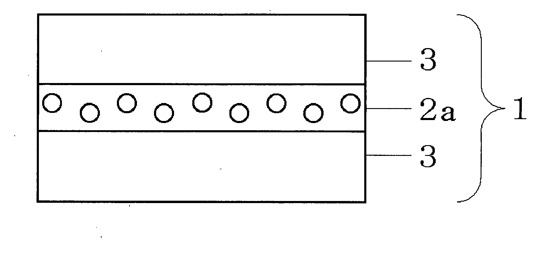
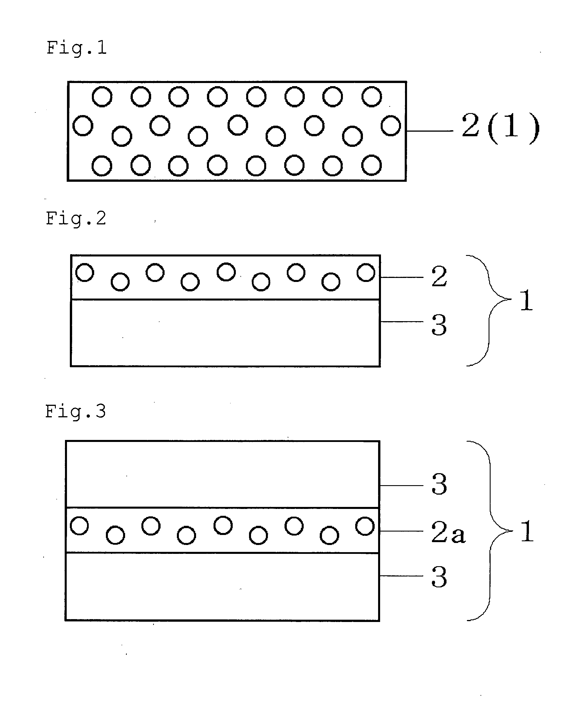
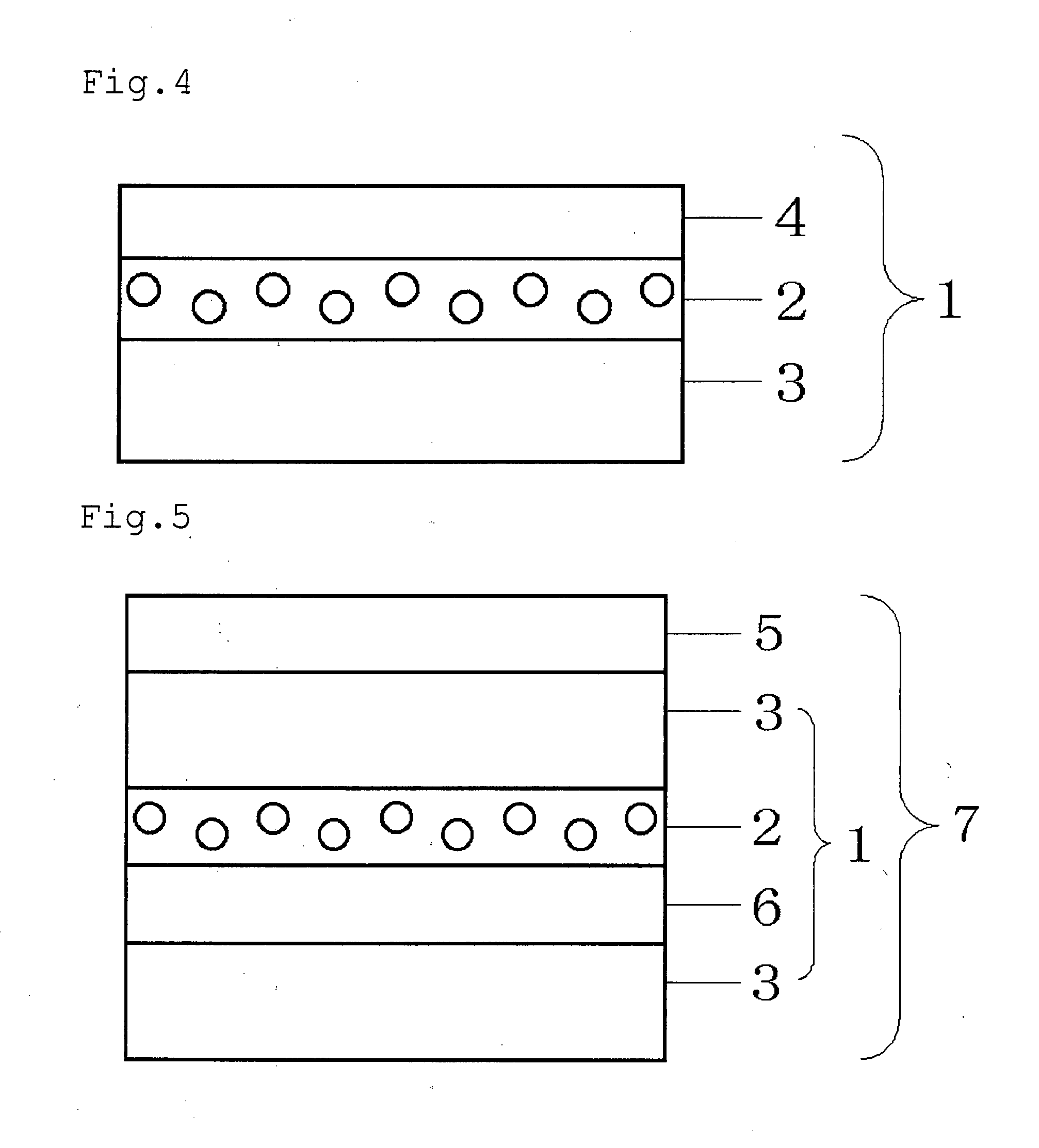
A light diffusing body and transmission type screen, which can reduce the shift of the color tone of the light source light seen through the light diffusing body and prevent the phenomenon that the white light source seen through the light diffusing body looks colored, is provide.The light diffusing body 1 of the present invention comprises a transparent resin and spherical micro-particles having a different refractive index from that of the said transparent resin, wherein the relation between the maximum value (Emax) and the minimum value (Emax) of the effective scattering efficiency values (E) obtained for each center wavelength in the wavelength ranges of blue, green and red by dividing the sum of scattering cross-sections of all spherical micro-particles contained in the unit area of the aforementioned light diffusing body 1 by the sum of geometrical cross-sections of all these spherical micro-particles satisfies Emin / Emax≧0.90.

Description

TECHNICAL FIELD[0001]The present invention relates to a light diffusing body and a transmission type screen, which can reduce the shift of color tone of the light from a light source seen through the light diffusing body, and in particular a light diffusing body and a transmission type screen, which can prevent the phenomenon that a white light source looks colored when seen through the light diffusing body.BACKGROUND ART[0002]Light diffusing bodies have been conventionally used in various optical applications, including transmission type screens.[0003]A light diffusing body to be used in the transmission type screens requires the properties that the light source of a projector behind the screen is not directly seen through and that the brightness of the whole screen is not reduced. There have been proposed a light diffusing plate (refer to Patent document 1) and a transmission type screen (refer to Patent document 2), in which an optimal balance between the transmission and diffusi...

Claims


Application Information

Patent Timeline
IPC IPC(8): B32B3/02
CPCB32B27/00Y10T428/24488C08L33/06C08L2205/18G03B21/62C08L25/06Y10T428/24942B32B7/12B32B25/08B32B25/20B32B27/08B32B27/308B32B27/36B32B27/40B32B2255/10B32B2264/0214B32B2264/0228B32B2264/0235B32B2264/0292B32B2264/10B32B2307/412B32B2307/414B32B2307/518Y10T428/25C08L2666/04
Inventor KITAHARA, KEIICHIETORI, HIDEKIKIMURA, YOSHIHISA
Owner KIMOTO CO LTD
Learn More