Optical recording/reproducing method

a recording medium and optical recording technology, applied in optical recording/reproducing/erasing methods, instruments, photomechanical equipment, etc., can solve the problems of difficult to improve the long-term storage reliability of the medium, warpage and tilt of the optical recording medium, and achieve excellent optical recording/reproducing characteristics and simple film structure

Inactive Publication Date: 2007-08-16
TDK CORPARATION
View PDF7 Cites 3 Cited by
  • Summary
  • Abstract
  • Description
  • Claims
  • Application Information

AI Technical Summary

Benefits of technology

[0017] As a result of an intensive study, the inventor has found that a simple film structure using environmentally friendly materials such as Sn and ZnS can provide excellent optical recording / reproducing characteristics. At the same time, the inventor has found that if a dielectric material and a state-change assisting material are arrayed adjacent to each other in the form of clusters and an energy beam like a laser beam is irradiated thereon, the cluster size of the dielectric material grows and its optical characteristics make a change.

Problems solved by technology

Since organic dyes degrade when exposed to sunlight, for example, it is not easy to improve long-term storage reliability of the medium using such an organic dye in the recording layer thereof.
On the other hand, if the NA of the object lens is raised to focus the laser beam, such a problem arises that the tolerance of warpage and tilt of the optical recording medium, namely, the tilt margin becomes very small.
Thus, in the next-generation type optical recording media, different from the currently-used optical recording media such as CD and DVD, it is difficult to form a recording layer and the like on the light transmission layer (transparent substrate).
However, a problem is found that when the recording layer is made of two reaction layers deposited on the substrate in the next-generation optical recording media the noise level is likely to become high (the C / N ratio becomes small) during signal restoration, compared with the conventional optical recording media such as CD and DVD where the recording layer formed in the light transmission layer (transparent substrate) is made of two reaction layers.

Method used


Image

  • Optical recording/reproducing method
  • Optical recording/reproducing method
  • Optical recording/reproducing method

Examples


examples and compared examples

[0088] Now the present invention will be explained more specifically along with some examples, but the invention is not limited to those examples.

[Preparation of the Optical Recording Medium]

Example(s) 1-3

[0089] Optical recording media were fabricated via the following steps.

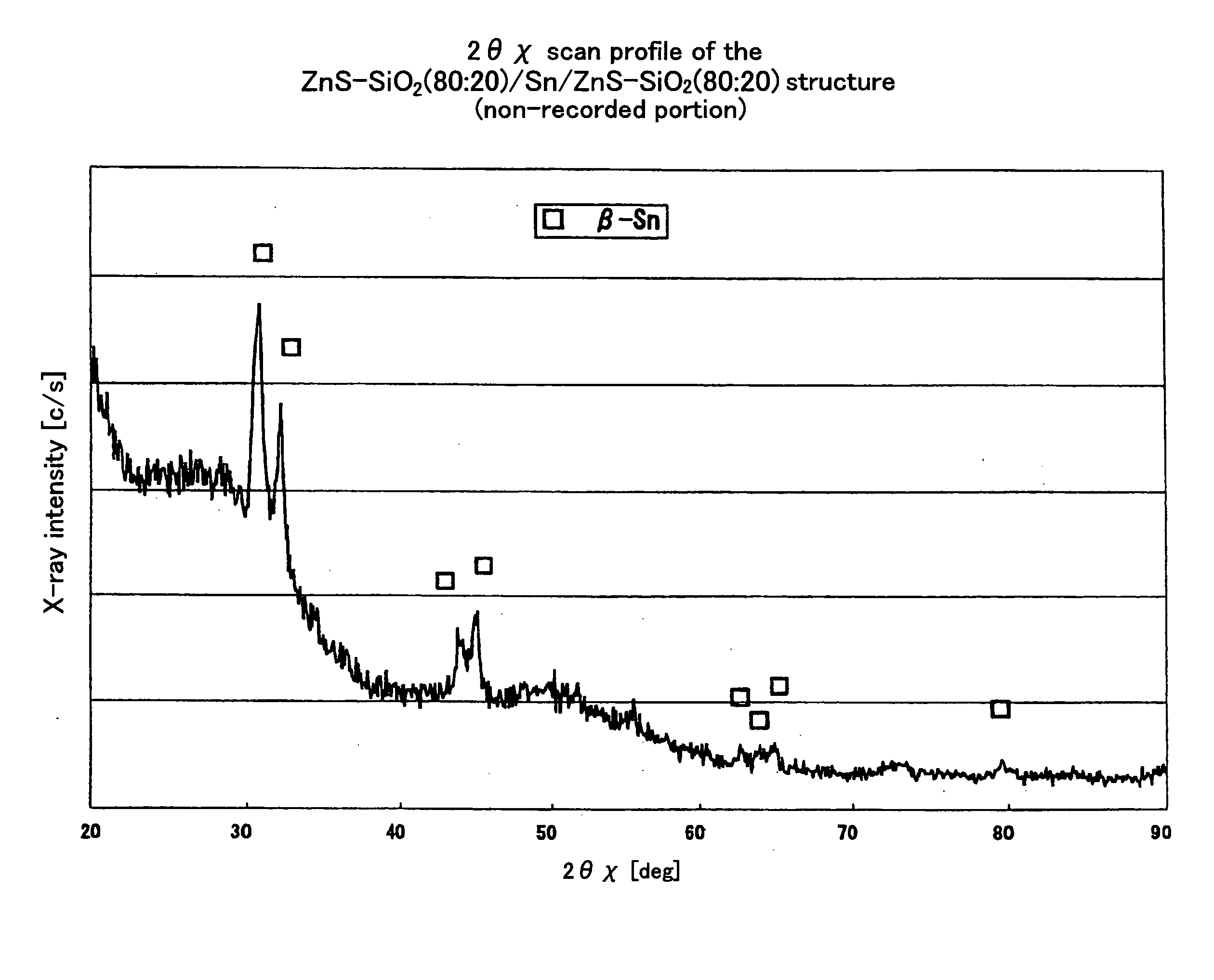
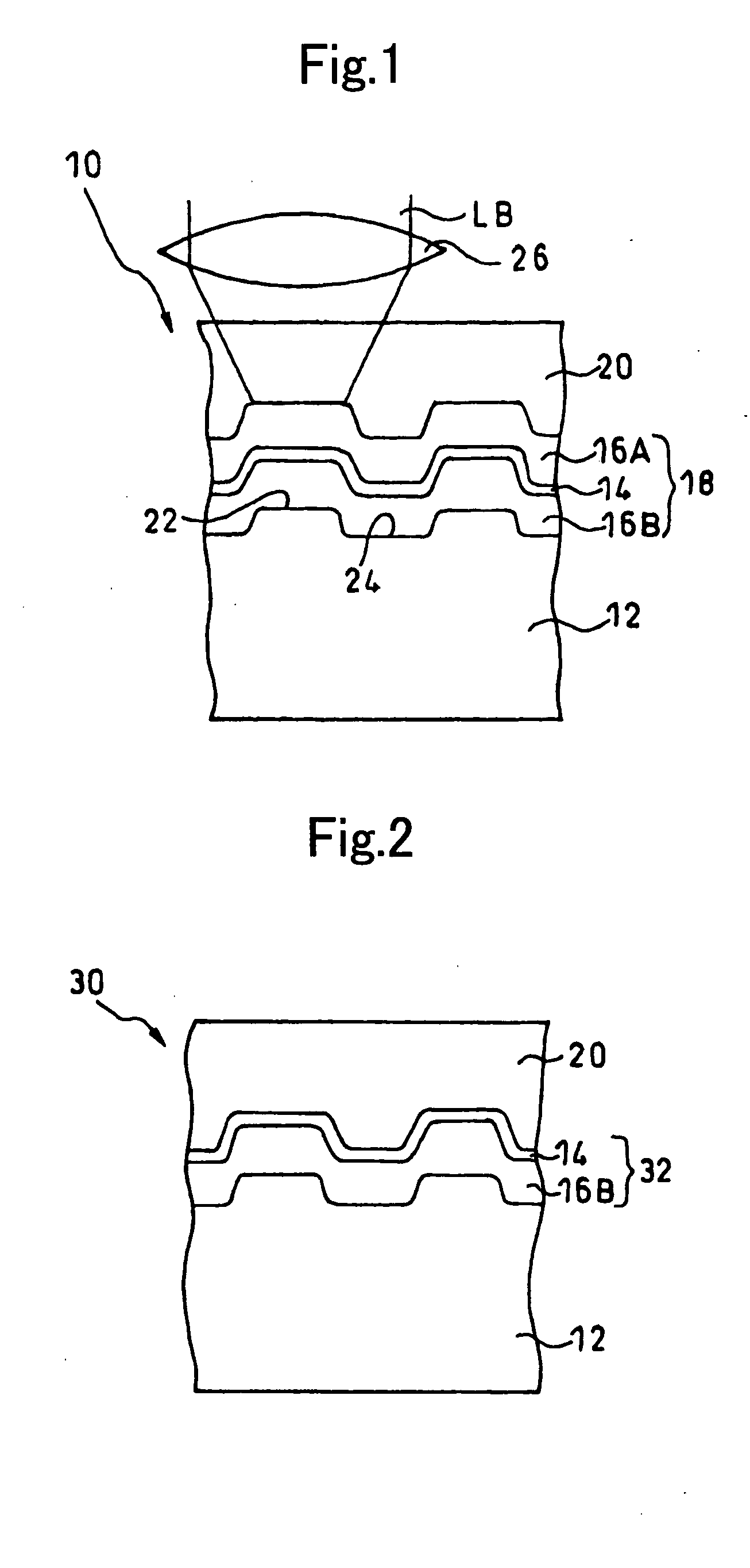
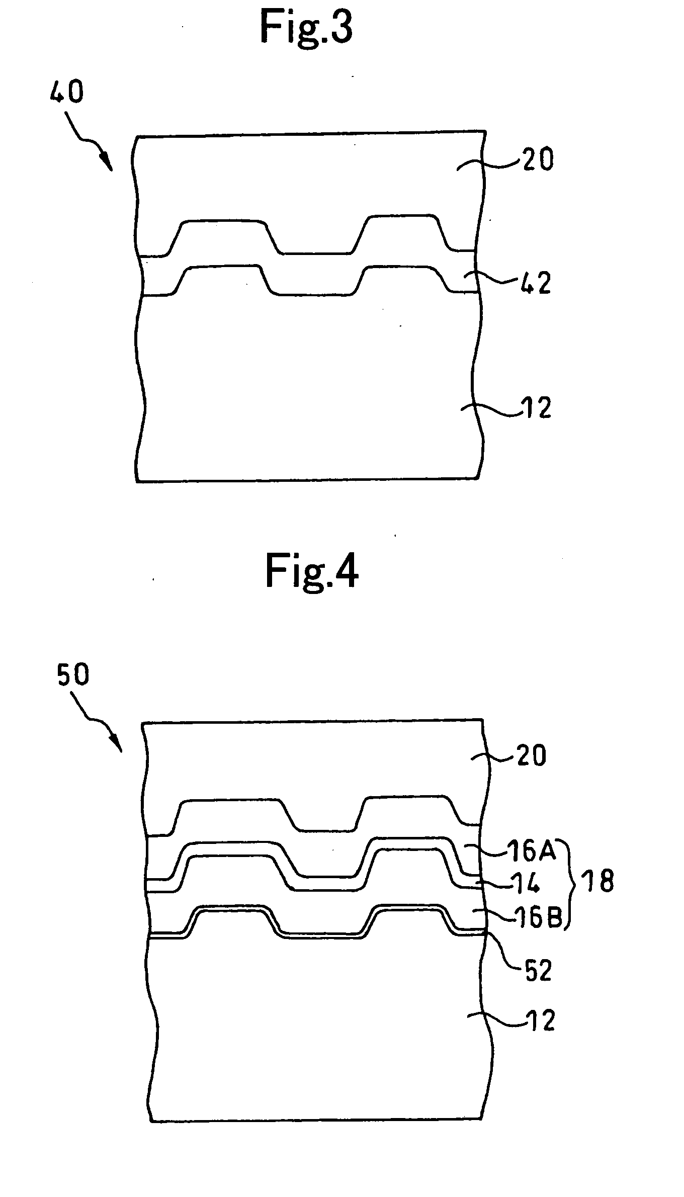
[0090] First, a polycarbonate substrate of which thickness was 1.1 mm and diameter was 120 mm was set in a sputtering apparatus. On the light reflection layer (only in example 2) of this polycarbonate substrate, the second dielectric layer made of a mixture of ZnS and SiO2, the state-change assisting layer made of Sn and the first dielectric layer (only in examples 1 and 2) made of a mixture of ZnS and SiO2 were formed one after another by the sputtering method. Here, the first dielectric layer and the second dielectric layer are a base material and a state change material.

[0091] Next, on the first dielectric layer, an acrylic ultraviolet-curable resin was coated by the spin coating method and the light tra...

examples 15

[0095] The optical recording medium with a single-layered recording layer was fabricated without forming any dielectric layer. The recording layer was made of a mixture of Sn and a dielectric material of ZnS:SiO2=80:20.

Example(s) 16, 17

[0096] The optical recording medium was fabricated in the same manner as the example 15 except that Sn employed in the example 15 was replaced by Ag or Ti.

compared example 4

[0097] The optical recording medium was fabricated in the same manner as the example 15 except that ZnS—SiO2 in the example 15 was omitted.

Example(s) 18-21

[0098] The optical recording medium was fabricated by changing the material for the dielectric layer and forming the state-change assisting layer made of Sn.

Example(s) 22-30

[0099] The optical recording medium with a recording layer of a single-layer structure was fabricated without forming any dielectric layer. The recording layer was made of a mixture of ZnS—SiO2 (ZnS:SiO2=80:20) and a metal or semi-metal of Mg, Nb, Bi, Mg, Au, Al, Au, Cu, Ta, or Si.

Example(s) 31-52

[0100] The optical recording media were fabricated by replacing ZnS—SiO2 (ZnS:SiO2=80:20) employed in the examples 22-30 to other materials. Mg (examples 31-35), Ti (examples 36-43), Sn (examples 44, 45), Nb (examples 46-48), or Al (examples 49-52) was mixed in the optical recording medium.

Example(s) 53-55

[0101] The optical recording medium with a recording lay...


PUM

PropertyMeasurementUnit
wavelengthaaaaaaaaaa
outer diameteraaaaaaaaaa

Abstract

An optical recording/reproducing method and an optical recording medium capable of performing excellent optical recording with a simple structure in a recording layer made of environmentally friendly materials. The optical recording medium has a recording layer on a substrate. The recording layer has a pair of dielectric layers of which states are altered by a laser beam that is an energy beam of which intensity is modulated according to information to be recorded. This recording layer also has a state-change assisting layer sandwiched by these dielectric layers. The state-change assisting layer includes an element selected from Sn, Ti, Si, Bi, Ge, and C as a principle component, while the dielectric material as a base material for the dielectric layers is at least one of ZnS, SiO2, AlN, and Ta2O5.

Description

[0001] This as a Division of application Ser. No. 10 / 446,732 filed May 29, 2003. The disclosure of the prior application is hereby incorporated by reference herein in its entirety. BACKGROUND OF THE INVENTION [0002] 1. Field of the Invention [0003] The present invention relates to an optical recording medium and an optical recording / reproducing method using the same. [0004] 2. Related Art [0005] As recording media for recording digital data, optical recording media such as CD (Compact Disc) and DVD (Digital Versatile Disc) have been widely used. These optical recording media can be broadly classified into the ROM-type optical recording media such as CD-ROM (Read Only Memory) and DVD-ROM where data is not added or rewritable, the write-once type optical recording media such as CD-R (Recordable) and DVD-R where data can be added but not rewritable, and the rewritable optical recording media such as CD-RW (Rewritable) and DVD-RW where data is rewritable. [0006] As well known, in the RO...

Claims


Application Information

Patent Timeline
Patent Type & Authority Applications(United States)
IPC IPC(8): G11B7/24G11B7/00G11B7/004G11B7/0045G11B7/20G11B7/243G11B7/253G11B7/26
CPCG11B7/00454G11B7/00455G11B7/243G11B7/253G11B2007/24304G11B2007/24306G11B2007/24328G11B2007/2431G11B2007/24312G11B2007/24314G11B2007/2432G11B2007/24324G11B2007/24308G11B7/005
Inventor INOUE, HIROYASUMISHIMA, KOJISUZAWA, KAZUKI
Owner TDK CORPARATION
Why Eureka
Try Eureka