Fiber optic strain gage

a strain gage and fiber optic technology, applied in the field of fiber optic strain gage, can solve the problems of loss of sensitivity, loss of measurement accuracy, and degrading gage performance, and achieve the effects of not degrading gage performance, low resistance to strain, and quick and easy attachmen

Inactive Publication Date: 2007-08-23
MICRON OPTICS
View PDF28 Cites 70 Cited by
  • Summary
  • Abstract
  • Description
  • Claims
  • Application Information

AI Technical Summary

Benefits of technology

[0010] The present invention provides a fiber optic strain gage that provides the benefits of a pre-mounted strain gage without degrading gage performance. The gage is quickly and easily attached to a test specimen. The gage includes a carrier having means for attachment to the test specimen, and means for holding a continuous length of optical fiber. The carrier is made of any appropriate material including metal, ceramic or plastic. In a specific embodiment, the carrier is a metal carrier. In another embodiment, the carrier is made of metal that can be welde...

Problems solved by technology

Although the use of a carrier for such gages significantly improves handling and mounting, its use can also degrade gage performance.
This can result in a loss of sensitivity.
Distorti...

Method used


Image

  • Fiber optic strain gage
  • Fiber optic strain gage
  • Fiber optic strain gage

Examples


Embodiment Construction

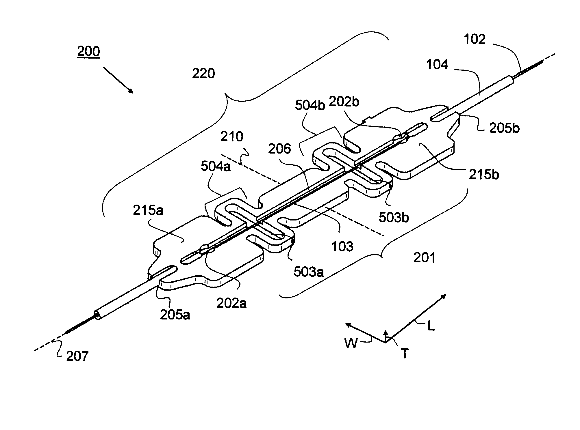
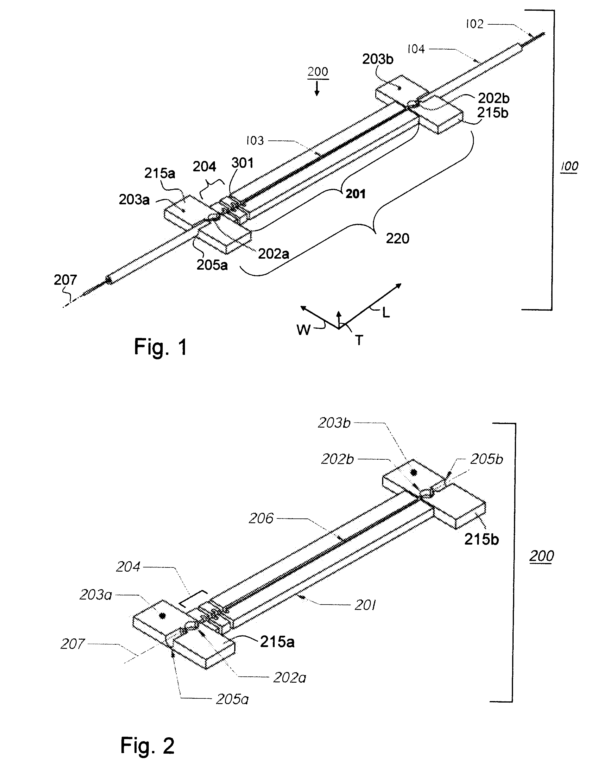
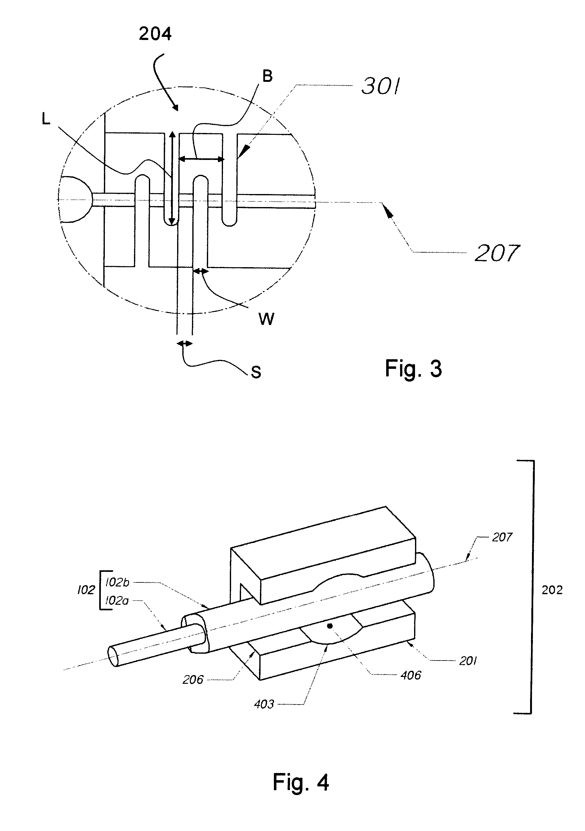
[0026] Referring to the drawings, like numerals indicate like elements and the same number appearing in more than one drawing refers to the same element. In addition the following definitions apply:

[0027]“Elastic” refers to the capability of a material, object, device or device component to increase or decrease size with respect to one or more physical dimensions. Elastic materials may be extensible, compressible or both. Elasticity refers to a characteristic of a material, object, device or device component having elasticity.

[0028]“Rigid” refers to a material deficient in or devoid of elasticity.

[0029]“Unitary body” refers to a body or object made up of a continuous or contiguous piece of material or made up of separate components that are operationally attached to each other. Unitary bodies do not comprise physically separated, discontinuous elements. Preferred unitary bodies are fabricated from a single material. However, a unitary body may comprise a plurality of components t...


PUM


Abstract

Fiber optical gages that impart physical strain to an optical fiber by varying the tension applied axially to the fiber, which causes a change in the optical property of the light transmitted through the fiber. A gage carrier which provides the benefits of a metal carrier for ease of handling and mounting without degrading gage performance. At least a portion of the gage carrier is elastic with respect to expansion, compression or both along its longitudinal axis, thereby allowing for variation of the distance between the two points at which the gage carrier is attached to a test specimen. In a specific embodiment, the gage carrier functions as two independent rigid fiber fastening elements separated by a compliant or flexible member. The invention further provides fiber Bragg grating strain gages, which are particularly useful for monitoring ambient conditions and measuring physical properties and mechanical phenomena.

Description

CROSS-REFERENCE TO RELATED APPLICATIONS [0001] This application claims the benefit of U.S. provisional application Ser. No. 60 / 765,547, filed Feb. 6, 2006. This application is incorporated by reference herein in its entirety.BACKGROUND OF THE INVENTION [0002] In the past few years, fiber optic-based strain gages have gained acceptance in the market as an alternative to conventional electronic gages which are based, for example, on changes in electrical resistance, inductance or capacitance. In many applications, such as civil structure monitoring, down-hole oil and gas applications, as well as marine, and aerospace applications, fiber optic gages offer several advantages over conventional gages. Unlike electronic gages, fiber-based gages are not sensitive to electromagnetic interference and are well suited for use in electrically-noisy environments. Fiber-based gages are also readily multiplexed, allowing many gages to operate on a single fiber over long distances. Fiber-based gages...

Claims


Application Information

Patent Timeline
IPC IPC(8): G01L1/24
CPCG01B11/165G01B11/18G02B6/022G01K11/3206G01P15/093G01D5/26G01B11/16G01B11/00G02B6/00
Inventor FERGUSON, STEPHEN K.
Owner MICRON OPTICS
Why Eureka
Try Eureka