
Method and system for controlling an internal combustion engine
a technology of internal combustion engine and control method, which is applied in the direction of electric control, fluid pressure control, instruments, etc., can solve the problems of inaccurate determination of loss torque, achieve high degree of accuracy, improve accuracy of estimated drive torque, and achieve accurate determination of target torque
Patent Information
- Authority / Receiving Office
- US · United States
- Patent Type
- Applications(United States)
- Current Assignee / Owner
- Publication Date
- 2007-08-23
Smart Images
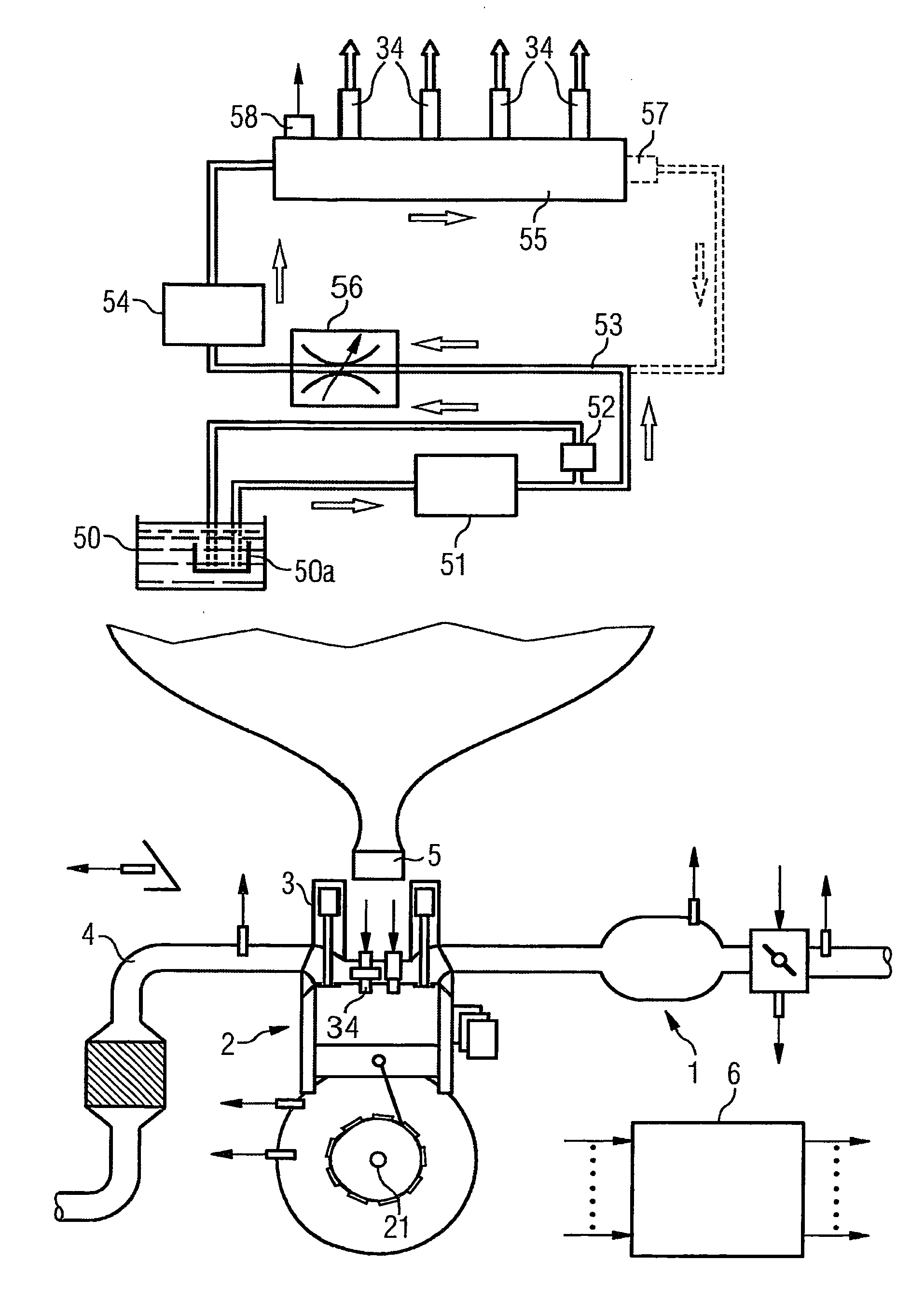
Figure 1 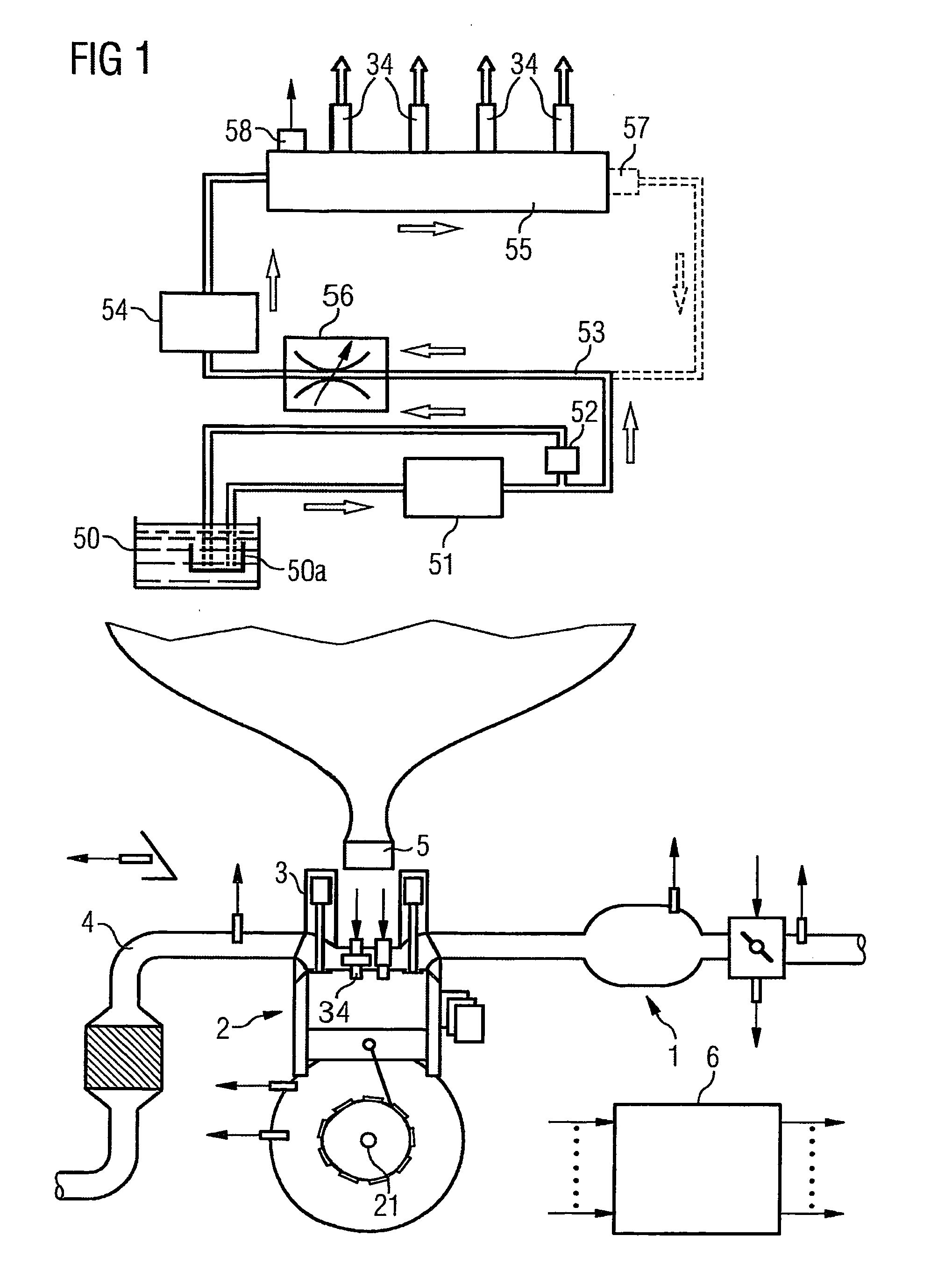
Figure 2 
Figure 3
Abstract
Description
CROSS REFERENCE TO RELATED APPLICATIONS
[0001] This application is the U.S. National Stage of International Application No. PCT / EP2005 / 050493, filed Feb. 4, 2005 and claims the benefit thereof. The International Application claims the benefits of German application No. 102004012489.2 DE filed Mar. 15, 2004. A11 of the applications are incorporated by reference herein in their entirety.FIELD OF INVENTION
[0002] The invention relates to a method for controlling an internal combustion engine. BACKGROUND OF INVENTION
[0003] Bearing in mind the increasingly strict statutory regulations on the exhaust emissions of internal combustion engines and because of, at the same time, increasing customer demands with regard to a high driving comfort, internal combustion engines in motor vehicles must be controlled increasingly accurately. Sensors, such as for example temperature sensors, speed sensors, mass air flow sensors or pressure sensors measure the physical operating variables of internal co...
Examples
Embodiment Construction
[0020] Elements with the same design and function are labelled in all the figures with the same reference symbols.
[0021] An internal combustion engine (FIG. 1) comprises an intake tract 1, an engine block 2, a cylinder head 3 and an exhaust gas tract 4. The engine block 2 comprises a number of cylinders, which have pistons and connecting rods by means of which they are connected to a crankshaft 21.
[0022] The cylinder head 3 comprises valve drive with a gas intake valve, a gas exhaust valve and valve gears. Furthermore, the cylinder head 3 also comprises both an injection valve 34 and a spark plug.
[0023] In addition, a supply device 5 for fuel is provided. It comprises a fuel tank 50, which is connected to a low-pressure pump 51 via a first fuel line. The fuel line opens into a fuel baffle 50a. On the outlet side, the low-pressure pump 51 has an operative connection to an intake 53 of a high-pressure pump 54. In addition, on the outlet side of the low-pressure pump 51, provision i...