Method of manufacturing multifocal lens and multifocal lens

a manufacturing method and lens technology, applied in the field of multi-focal lenses, can solve the problems of high manufacturing cost, difficult to polish optical surfaces, and difficult to align the optical axes of two kinds of lenses, and achieve the effects of reducing interface damage, superior optical characteristic, and stable optical characteristi

Inactive Publication Date: 2007-08-23
SEIKO EPSON CORP
View PDF6 Cites 55 Cited by
  • Summary
  • Abstract
  • Description
  • Claims
  • Application Information

AI Technical Summary

Benefits of technology

[0013]According to a first aspect of the invention, a multifocal lens includes a group including M layered lenses. M-kinds (M is an integer of two or more) of lens materials having glass deformation point temperatures of At1, At2, . . . , AtM, are used and diluted by a heat press method. Further, a contact surface of an N−1th lens (N is an arbitrary integer of two or more and M or less) contacted with an Nth lens is a concave face, a contact surface of the Nth lens contacted with the N−1th lens is a convex face. The glass deformation point temperatures have a relation of AtN-1>AtN.
[0014]According to the first aspect, the glass deformation point temperature AtN-1 of the N−1th lens is higher than the glass deformation point temperature AtN of the Nth lens. Thus, when the Nth lens is heat-pressed, the contact surface of the N−1th lens can be used as a part of a molding die. When the contact surface of the N−1th lens is a concave face, compression stress is applied to the Nth lens material having a fluid state thermally diluted in the vicinity of the contact surface of the N−1th lens. When the contact surface of the N−1th lens has a convex face on the contrary, tensile stress is applied to the surface of the Nth lens material having a fluid state thermally diluted in the vicinity of the contact surface of the N−1th lens. In the multifocal lens of the aspect, compression stress is applied to the center direction of the convex face of the Nth lens material. Thus, when compared with a case where tensile stress is applied, contact of an interface between the Nth lens and the N−1th lens is less influenced. This can provide a superior optical characteristic and can reduce damages in the interface such as crack and peeling.
[0015]By providing the above-described shape to t

Problems solved by technology

However, in the case of the lenses A and B shown in FIGS. 35(A) and 35(B), it is very difficult to polish optical surfaces A1 and B1 since they include faces A2 and B2 having different curvatures.
Furthermore, in the case of the lens B shown in FIG. 35(B), it is also very difficult to align optical axes of two kinds of lenses since adhesive agent bonds them.
In the case of the lens C shown in FIG. 35(C), a structure composed of peripheral parts C1 and a center part C2 requires a complicated process, causing a very high manufacture cost.
Furthermore, in designing these multifocal lenses, realizing a multi

Method used


Image

  • Method of manufacturing multifocal lens and multifocal lens
  • Method of manufacturing multifocal lens and multifocal lens
  • Method of manufacturing multifocal lens and multifocal lens

Examples


embodiment 1

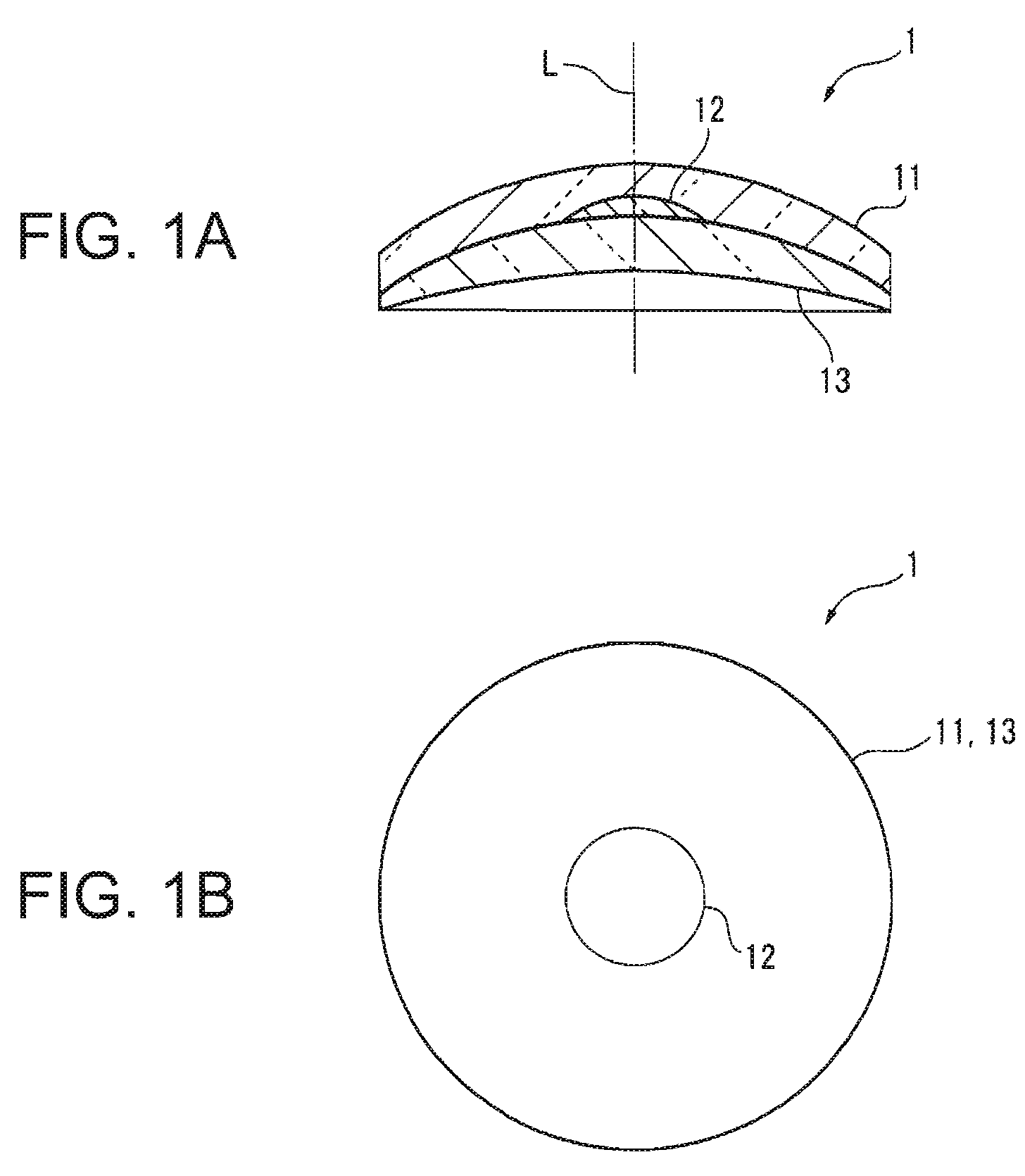
[0086]FIG. 1 to FIG. 7 show Embodiment 1 of the invention. Embodiment 1 is a multifocal lens 1 having a structure in which one group includes three layers.

[0087]FIG. 1 shows the multifocal lens 1 of Embodiment 1. This multifocal lens 1 is structured, as show n in the cross-sectional view of FIG. 1(A), a to have a layered structure including from the convex face side, the first lens 11 having a glass deformation point temperature At1 (hereinafter may be simply referred to as “lens 11”), the second lens 12 having a glass deformation point temperature At2 (hereinafter may be simply referred to as “lens 12”), and the third lens 13 having a glass deformation point temperature At3 (hereinafter may be simply referred to as “lens 13”). Here, the above-described glass deformation point temperatures At1, At2, and At3 have a relation of At1>At2>At3. The respective lenses have glass transition temperatures for which a relation of Tg1>Tg2>Tg3 is established and relations of Tg1>At2 and Tg2>At3 a...

embodiment 2

[0115]Next, Embodiment 2 of the invention will be described with reference to FIGS. 8(A) and 8(B) and FIG. 9. Embodiment 2 has the same structure as that of Embodiment 1 except for that the number and lay-out of lenses positioned at an intermediate position.

[0116]As shown in FIGS. 8(A) and 8(B), a multifocal lens 2 having a structure in which one group includes three layers of Embodiment 2 is composed of three layers of a lens 21, a lens 22, and a lens 23. The lens 22 positioned at an intermediate position is positioned so as to be dislocated from the optical axes of the lenses 21 and 23. Although Embodiment 2 arranges the four lenses 22 on a concentric circle around the optical axis as shown in FIG. 8(B), the lenses 22 are not always required to be on the concentric circle and an arbitrary number of lenses 22 also can be arranged at arbitrary positions in accordance with the optical characteristic of the multifocal lens 2.

[0117]The multifocal lens 2 as described above also can be m...

embodiment 3

[0119]Next, Embodiment 3 of the invention will be described with reference to FIGS. 10(A) and 10(B) and FIGS. 11(A) and 11(B). Embodiment 3 has the same structure as that of Embodiment 1 except for the shape of the lens at the intermediate position.

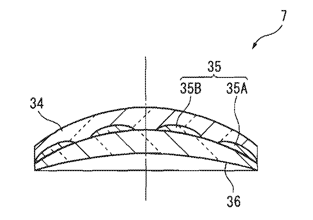
[0120]In a multifocal lens 3 of Embodiment 3 shown in FIGS. 10(A) and 10(B), a lens 32 positioned at an intermediate position has a doughnut-like shape having no center part. The multifocal lens 3 as described above also can be manufactured by the above-described manufacture method.

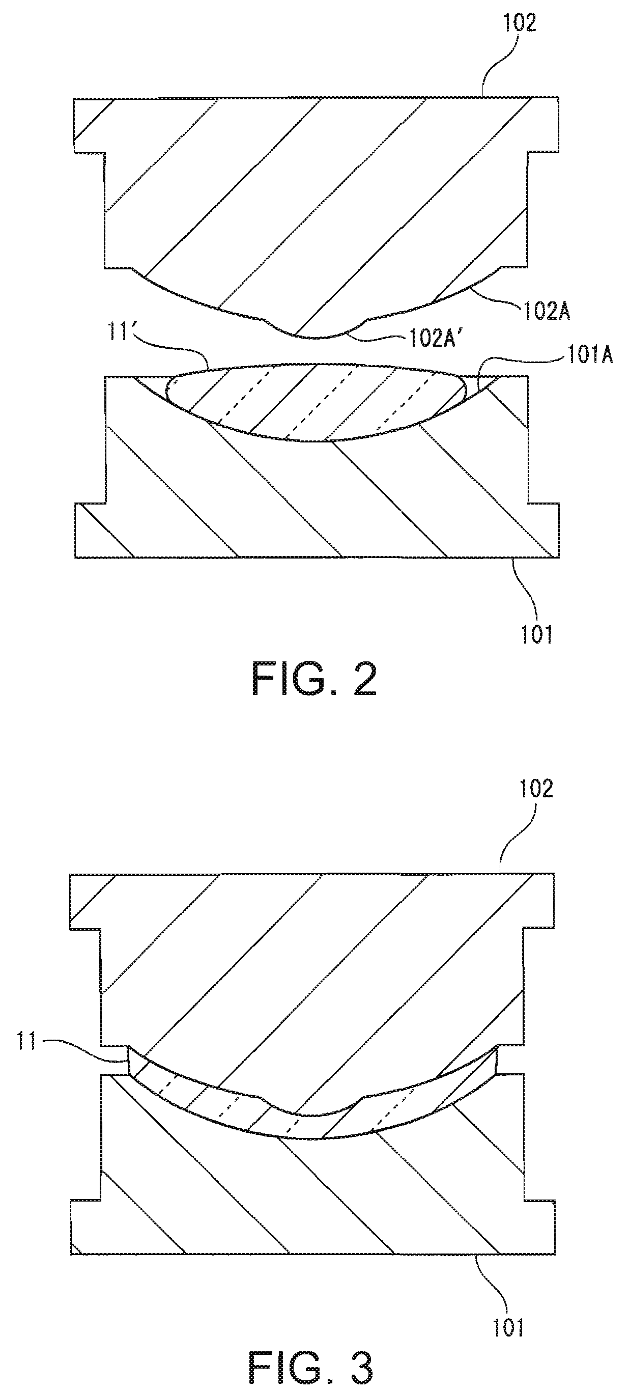
[0121]Specifically, as shown in FIGS. 11(A) and 11(B), the first lens 31 having the highest glass deformation point temperature is firstly formed. The first lens 31 includes a concave section 31A at a position at which the second lens 32 is placed. The posture of a lower metal mold 301 is controlled so that this concave section 31A faces upward.

[0122]The second lens material 32′ is shaped to have a doughnut-like disk having no center part as shown in FIGS. 11(A...


PUM


Abstract

A multifocal lens includes a group including M layered lenses. M-kinds (M is an integer of two or more) of lens materials having glass deformation point temperatures of At1, At2, . . . , AtM, are used and diluted by a heat press method. A contact surface of an N−1th lens (N is an arbitrary integer of two or more and M or less) contacted with an Nth lens is a concave face, a contact surface of the Nth lens contacted with the N−1th lens is a convex face. The glass deformation point temperatures have a relation of AtN-1>AtN.

Description

BACKGROUND OF THE INVENTION[0001]1. Technical Field[0002]The present invention relates to a multifocal lens and a method of manufacturing it.[0003]2. Related Art[0004]Conventionally, lenses as an optical component have been widely used for glasses and cameras for example. A lens is classified to a fixed length focal lens having only one focal point and a multifocal lens having a plurality of focal points.[0005]Various multifocal lenses have been suggested such as a lens A as shown in FIG. 35(A) in which an optical surface partially includes a region having a different curvature, a lens B as shown in FIG. 35(B) in which an optical surface is partially attached with another lens by adhesive agent, or a lens C as shown in FIG. 35(C) in which peripheral parts and the center part of the lens bonded to one another are made of different materials (see JP-A-H11-023809 for example).[0006]On the other hand, a method of manufacturing a layered fixed length focal lens has been suggested in whic...

Claims


Application Information

Patent Timeline
IPC IPC(8): G02C7/06
CPCG02B3/10B29D11/00028B29D11/0049
Inventor SHIMIZU, AKIHIRONISHI, KOTAGOTO, YOSHITAKAMIYAZAWA, TAKANORI
Owner SEIKO EPSON CORP
Why Eureka
Try Eureka