High-frequency heating device

a high-frequency heating and magnetron technology, applied in the direction of electric/magnetic/electromagnetic heating, process and machine control, etc., can solve the problems of unnecessary loss and noise, heavy and large conventional power supplies mounted on high-frequency heating apparatus, failure of semiconductor switching device, etc., and achieve the effect of no unnecessary energy consumption

Active Publication Date: 2007-08-23
PANASONIC CORP
View PDF5 Cites 25 Cited by
  • Summary
  • Abstract
  • Description
  • Claims
  • Application Information

AI Technical Summary

Benefits of technology

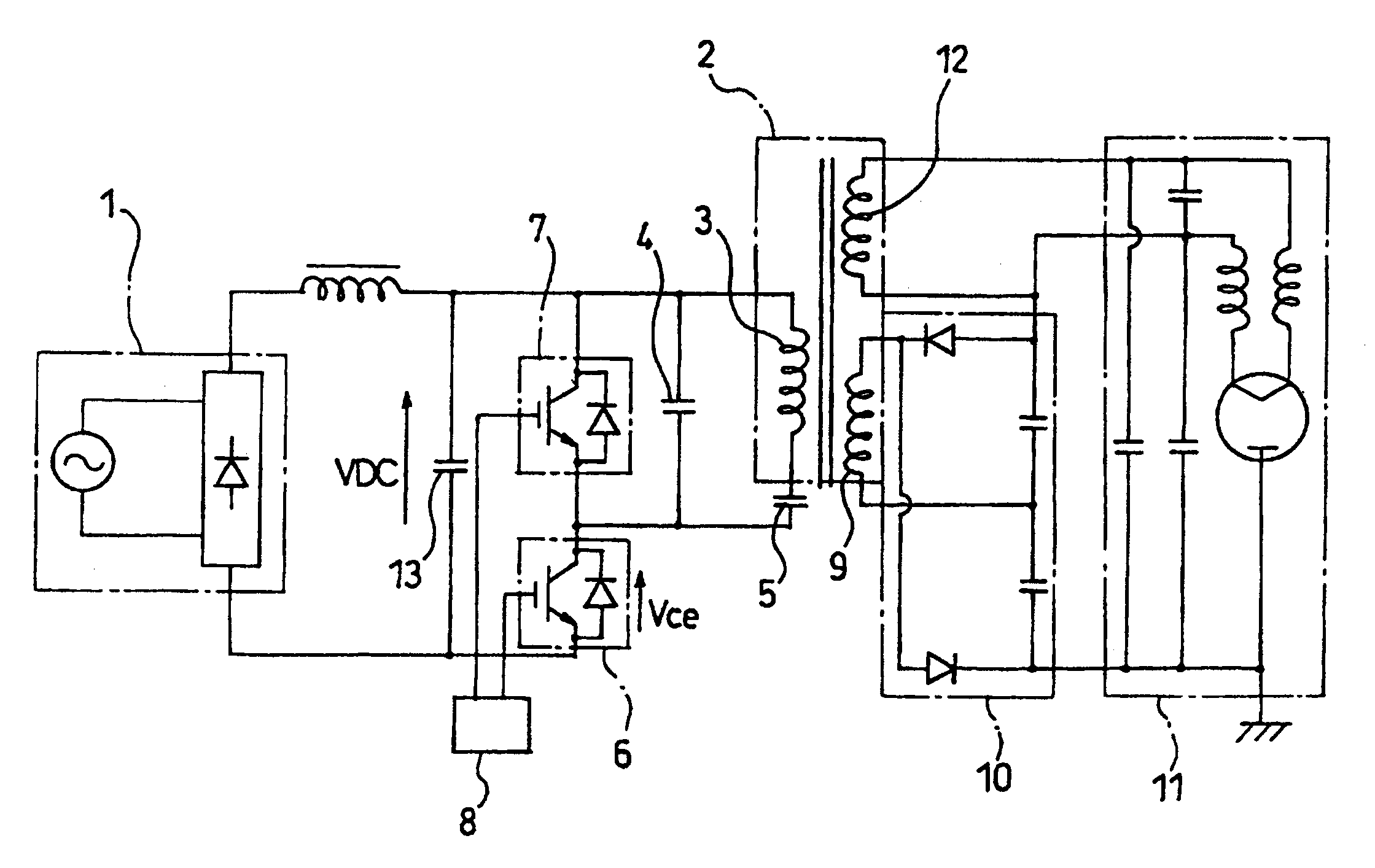
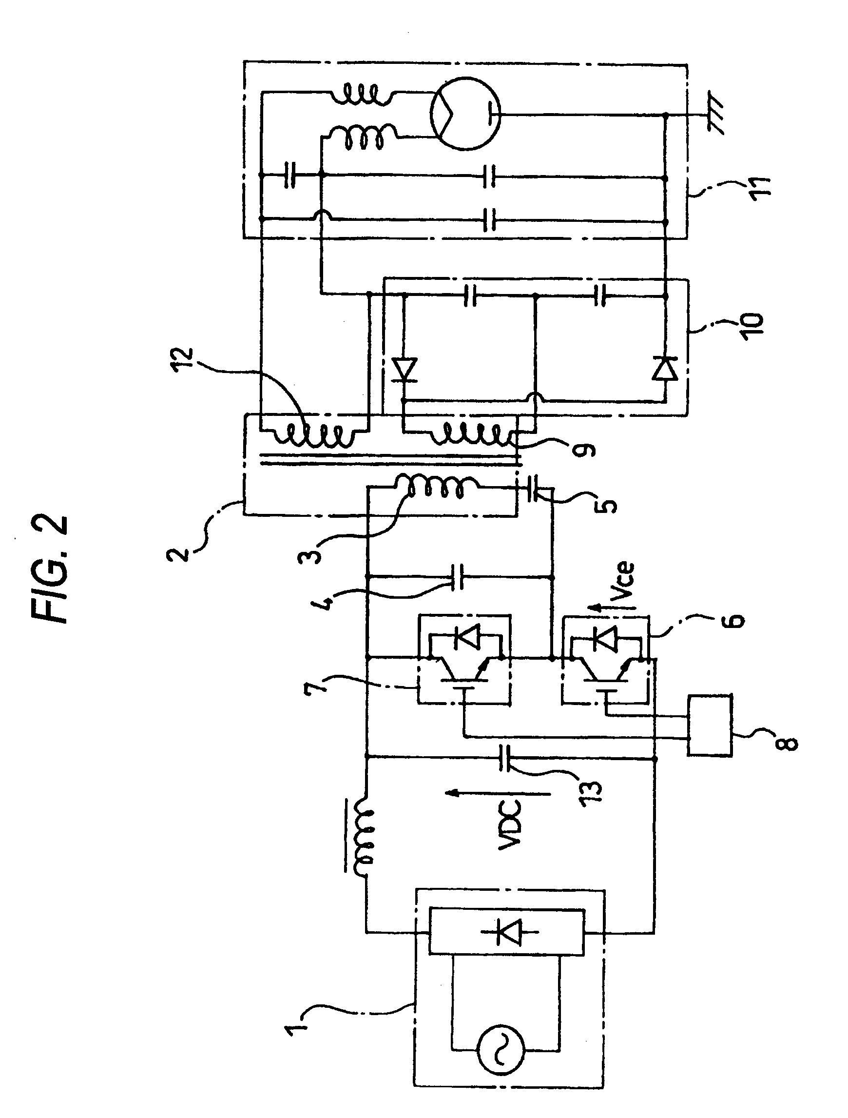
[0063] With such a configuration, it is possible to obtain an inverter circuit in which short-circuit of a power supply is prevented from occurring, heat loss hardly occurs in IGBTs, therefore no useless energy is consumed, and noise hardly occurs, and in which soft start can be implemented by a simple circuit added thereto.

Problems solved by technology

Conventional power supplies mounted on high-frequency heating apparatus were heavy and large.
When the other semiconductor switching device is turned on in this event, a spike-like overcurrent flows so that unnecessary loss and noise occur.
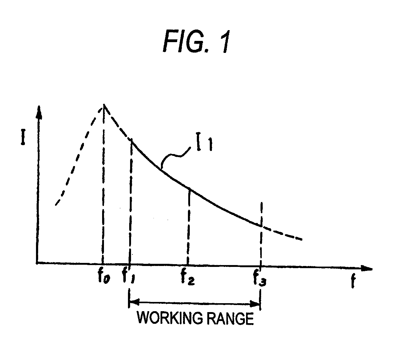
When the switching frequency is high, heat loss may occur in the semiconductor switching devices, causing a failure in the semiconductor switching devices or occurrence of a spike current breeding noise.
Thus, heat loss occurs.
Therefore, in the background-art inverter circuit, the adverse effect of hard switching has been unchallenged at all.

Method used


Image

  • High-frequency heating device
  • High-frequency heating device
  • High-frequency heating device

Examples


first embodiment

[0110]FIG. 6 shows a lowest frequency limiting circuit for carrying out soft start.

[0111] In FIG. 6, the reference numeral 221 represents a lowest frequency limiting circuit according to the first embodiment. This lowest frequency limiting circuit 221 has a transistor 221a, resistors 221b, 221d and 221e, a capacitor 221c, a switch 221f and an amplifier 221g. The emitter, collector and base of the transistor 221a are connected to the resistor 221b, a power supply Vcc, and the capacitor 221c, respectively. One end of the resistor 221b is connected to the output side of the frequency-modulated signal generation circuit 22, and the other end thereof is connected to the emitter of the transistor 221a as mentioned above. One end of the capacitor 221c is connected to the base of the transistor 221a as mentioned above, and the other end thereof is connected to the ground. One end of the resistor 221e is connected to the power supply Vcc, and the other end thereof is connected to the ground ...

second embodiment

[0116]FIG. 7 shows a lowest frequency limiting circuit for carrying out soft start.

[0117] In FIG. 7, the reference numeral 222 represents a lowest frequency limiting circuit according to the second embodiment. This lowest frequency limiting circuit 222 has a transistor 222a, resistors 222b, 222d and 222e, a capacitor 222c, a switch 222f, an amplifier 222g, and a constant current source 222h. The emitter, collector and base of the transistor 222a are connected to the resistor 222b, a power supply Vcc, and the capacitor 222c, respectively. One end of the resistor 222b is connected to the output side of the frequency-modulated signal generation circuit 22, and the other end thereof is connected to the emitter of the transistor 222a as mentioned above. One end of the capacitor 222c is connected to the base of the transistor 222a as mentioned above, and the other end thereof is connected to the ground. One end of the resistor 222e is connected to the power supply Vcc, and the other end t...


PUM


Abstract

An object of the present invention is to provide an inverter circuit in which soft start can be implemented by a simple circuit added thereto. In high-frequency heating apparatus for driving a magnetron, a DC power supply is chopped by two semiconductor switching devices, and this is output as an AC current through a resonance circuit. The high-frequency heating apparatus includes a dead time generation circuit for turning off the semiconductor switching devices concurrently. In the high-frequency heating apparatus, a drive unit for driving the aforementioned semiconductor switching devices has a function of limiting the lowest frequency of a frequency with which the semiconductor switching devices are driven. The aforementioned lowest frequency is set to be high at the beginning of operation of the high-frequency heating apparatus, and the aforementioned lowest frequency is set to be lower gradually thereafter.

Description

TECHNICAL FIELD [0001] The present invention relates to high-frequency heating using a magnetron in a microwave oven or the like, particularly relates to an inverter circuit therefor. BACKGROUND ART [0002] Conventional power supplies mounted on high-frequency heating apparatus were heavy and large. It has been therefore demanded to make the power supplies smaller in size and lighter in weight. To this end, in various kinds of present fields, switching has been aggressively applied to power supplies to thereby make the power supplies smaller in size, lighter in weight and lower in price. In high-frequency heating apparatus for cooking foodstuffs by microwaves generated by magnetrons, there was a request to make power supplies for driving the magnetrons smaller in size and lighter in weight. The request was realized by switching in inverter circuits. [0003] Of the inverter circuits, a high-frequency inverter circuit aimed at by the present invention is based on a resonance type circui...

Claims


Application Information

Patent Timeline
Patent Type & Authority Applications(United States)
IPC IPC(8): H02M3/335H05B6/68
CPCH05B6/681H05B6/685Y02B40/143Y02B40/00
Inventor SUENAGA, HARUOMORIYA, HIDEAKISAKAI, SHINICHIMORIKAWA, HISASHIMATSUKURA, TOYOTSUGUSHIROKAWA, NOBUO
Owner PANASONIC CORP
Why Eureka
Try Eureka