
Networked multi-role robotic vehicle

Active Publication Date: 2007-08-23
DEERE & CO +1
View PDF49 Cites 219 Cited by
  • Summary
  • Abstract
  • Description
  • Claims
  • Application Information

AI Technical Summary

Benefits of technology

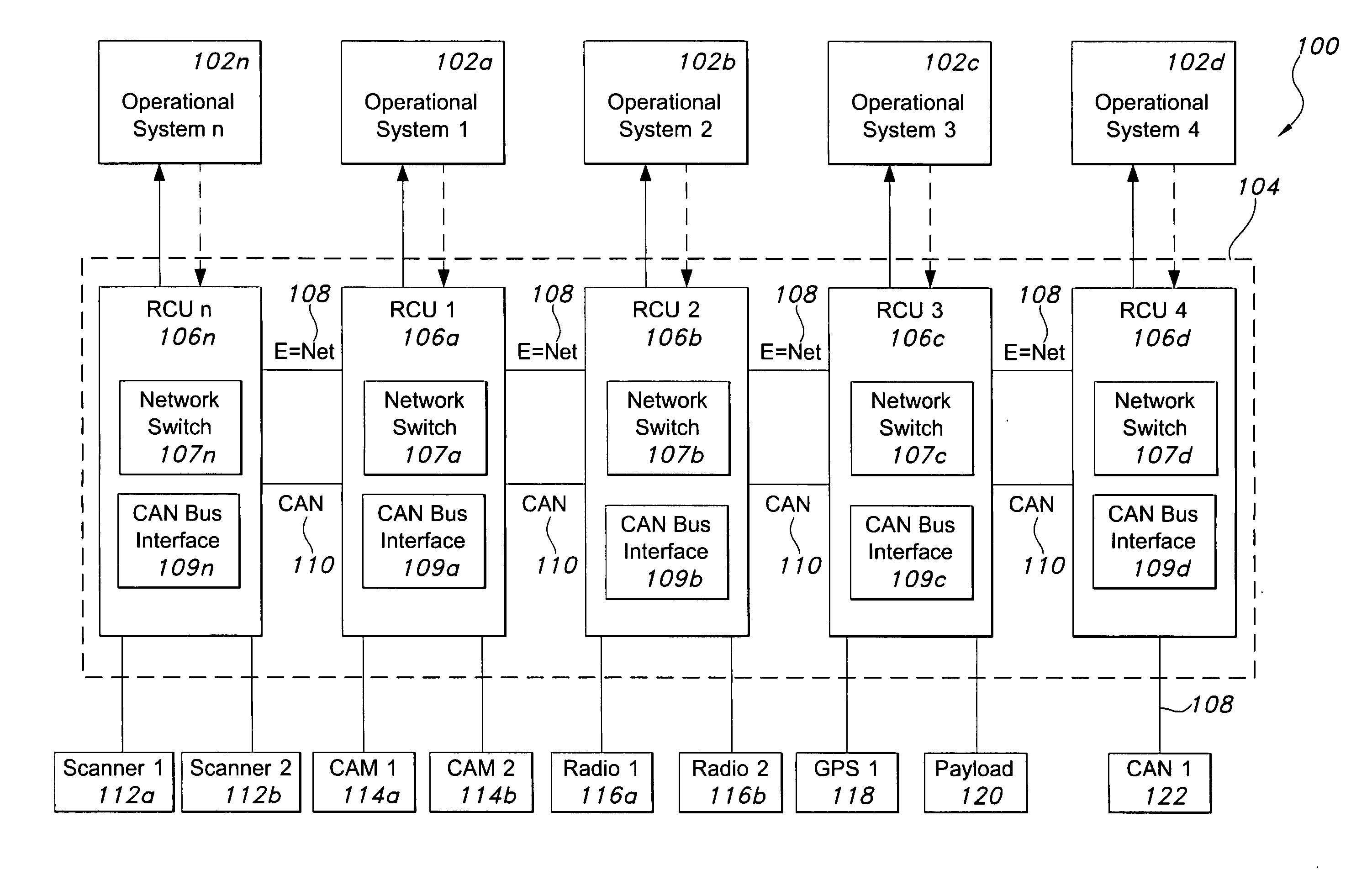
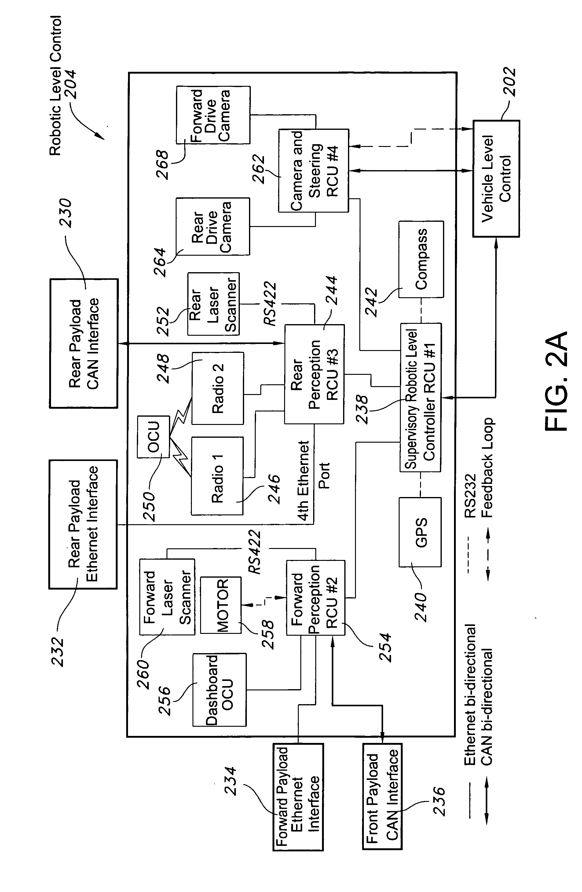
[0014] In certain embodiments, the RCU and / or VCU use a virtual terminal protocol to encapsulate Controller Area Network (CAN) or other types of data into one or more Ethernet packets. The RCU and / or VCU may then send the Ethernet packets to a dashboard OCU, remote OCU, or payload over at least one network. For example, there may be a local packet network such as an Ethernet network, and a vehicle control network such as a CAN network, or any combination of the two. The Ethernet network is useful for transferring data among the payload, actuators, sensors, and control, but is not usually the same physical layer that would be used for teleoperation of the vehicle. At the same time, it is useful for teleoperation of the vehicle if the Ethernet and CAN networks rely upon the same network protocols. Accordingly, the local packet network preferably has a first physical and / or data link layer and connects to a remote OCU with a second physical and / or data link layer, but each layer uses the same transport layer. For further flexibility, the packets of the vehicle control network may be tunneled through the transport layer, either among the payload bay, processor circuits, sensors, and or actuators on the vehicle, or to the remote OCU via radio. It is advantageous that the local packet network have connector(s) in the passenger compartment and in the truck bed so that payloads or systems may be plugged into the vehicle to communicate over the networks.

Problems solved by technology

In one embodiment, the payload bays are located in the truck bed because the payloads are bulky, and would interfere with passenger seating if placed within the seating area or in the glove box.

Method used


Image

  • Networked multi-role robotic vehicle
  • Networked multi-role robotic vehicle
  • Networked multi-role robotic vehicle

Examples


example 1

[0081] Message: Change Numeric Value;

[0082] Data Length: 8;

[0083] Byte 1: VT function=168;

[0084] Byte 2: Object ID of object to change (Least Significant Byte);

[0085] Byte 3: Object ID of object to change (Most Significant Byte);

[0086] Byte 4: 255; and

[0087] Byte 5-8: Numeric value (Values greater than 1 byte are transmitted Least Significant Bit first).

example 2

[0088] Message: Change String Value;

[0089] Data Length: Depends on string size;

[0090] Byte 1: VT function=179;

[0091] Byte 2: Object ID of object to change (Least Significant Byte);

[0092] Byte 3: Object ID of object to change (Most Significant Byte);

[0093] Byte 4: Total number of bytes in string to transfer (Least Significant Byte);

[0094] Byte 5: Total number of bytes in string to transfer (Most Significant Byte); and

[0095] Byte 6-n: String value (array of ASCII characters).

[0096] Virtual terminal protocol may also be used during communication between payloads and the vehicle's control system or any components that communicate on the vehicle's network. In box 282 of FIG. 19, the component receives the data transmitted by the RCU. In box 284, the component may process the data to determine the appropriate action to take in response to the data. Then in box 286, the component can take the necessary action, if needed. For example, a chemical detection payload may be connected to...


PUM


Abstract

An autonomous vehicle and systems having an interface for payloads that allows integration of various payloads with relative ease. There is a vehicle control system for controlling an autonomous vehicle, receiving data, and transmitting a control signal on at least one network. A payload is adapted to detachably connect to the autonomous vehicle, the payload comprising a network interface configured to receive the control signal from the vehicle control system over the at least one network. The vehicle control system may encapsulate payload data and transmit the payload data over the at least one network, including Ethernet or CAN networks. The payload may be a laser scanner, a radio, a chemical detection system, or a Global Positioning System unit. In certain embodiments, the payload is a camera mast unit, where the camera communicates with the autonomous vehicle control system to detect and avoid obstacles. The camera mast unit may be interchangeable, and may include structures for receiving additional payload components.

Description

RELATED PATENTS AND APPLICATIONS [0001] This application claims the benefit of U.S. Provisional Patent Application No. 60 / 729,445, filed Oct. 21, 2005, U.S. Provisional Patent Application No. 60 / 729,388, filed Oct. 21, 2005, U.S. Provisional Patent Application No. 60 / 780,389, filed Mar. 8, 2006, and U.S. Provisional Patent Application No. 60 / 838,704, filed Aug. 18, 2006, each of which is incorporated herein by reference in its entirety. [0002] This application is related to U.S. patent applications entitled “Robotic Control Module”[Attorney Docket No. 56516 / 335073]; “Systems and Methods for Obstacle Avoidance” [Attorney Docket No. 56516 / 335072]; and “Systems and Methods for Switching Between Autonomous and Manual Operation of a Vehicle” [Attorney Docket No. 56516 / 335074], each of which is filed herewith and incorporated herein by reference in its entirety. [0003] This invention also relates to U.S. Pat. No. 6,535,793 entitled “Method and System for Remote Control of Mobile Robot,” U...

Claims


Application Information

Patent Timeline
Patent Type & Authority Applications(United States)
IPC IPC(8): G01C22/00
CPCG05D1/0246Y10S901/47G05D1/0259G05D1/027G05D1/0272G05D1/0274G05D1/0278G05D1/028G05D2201/0201G05D2201/0202G05D2201/0209G05D2201/0213G05D2201/0216B60T7/22B60W30/09B60W30/095B62D1/286G05D1/0061G05D1/024G05B19/414G05D1/021Y10S901/01G05D1/0251G05D1/0088G05D1/02G05B19/042B60W60/0051B60W60/0053H04L67/12
Inventor NORRIS, WILLIAM ROBERTALLARD, JAMESPUHALLA, JEFFERY SCOTTWIENHOLD, KATHLEEN A.
Owner DEERE & CO
Learn More