Electromagnetic Interference Shields for Electronic Devices

a technology of electromagnetic interference and shields, applied in shielding materials, instruments, transportation and packaging, etc., can solve the problems of insufficient emi dissipation of conventional thin-film vacuum metallizing, inconvenient application of relatively thick thin-film equipment, etc., and achieve the effect of increasing the resistance of shielded components

Inactive Publication Date: 2007-08-30
WAVEZERO
View PDF99 Cites 25 Cited by
  • Summary
  • Abstract
  • Description
  • Claims
  • Application Information

AI Technical Summary

Benefits of technology

[0019] Use of these polymers with additional fillers such as carbon black, graphite, and metal fibers, add to the shielding effectiveness for absorbing more of the lower electro-magnetic wavelengths.
[0031] Another object of the invention is to provide an EMI shield which increases resistance of the shielded components to corrosive atmospheric conditions.

Problems solved by technology

Conventional thin-film vacuum metallizing is not adequate to dissipate EMI.
Existing equipment for metallizing thermoformed shapes for ornamental reflective appearance purposes is not suitable for application of relatively thick thin film as is required to provide suitable surface impedance to allow effective EMI dissipation.

Method used


Image

  • Electromagnetic Interference Shields for Electronic Devices
  • Electromagnetic Interference Shields for Electronic Devices
  • Electromagnetic Interference Shields for Electronic Devices

Examples


example

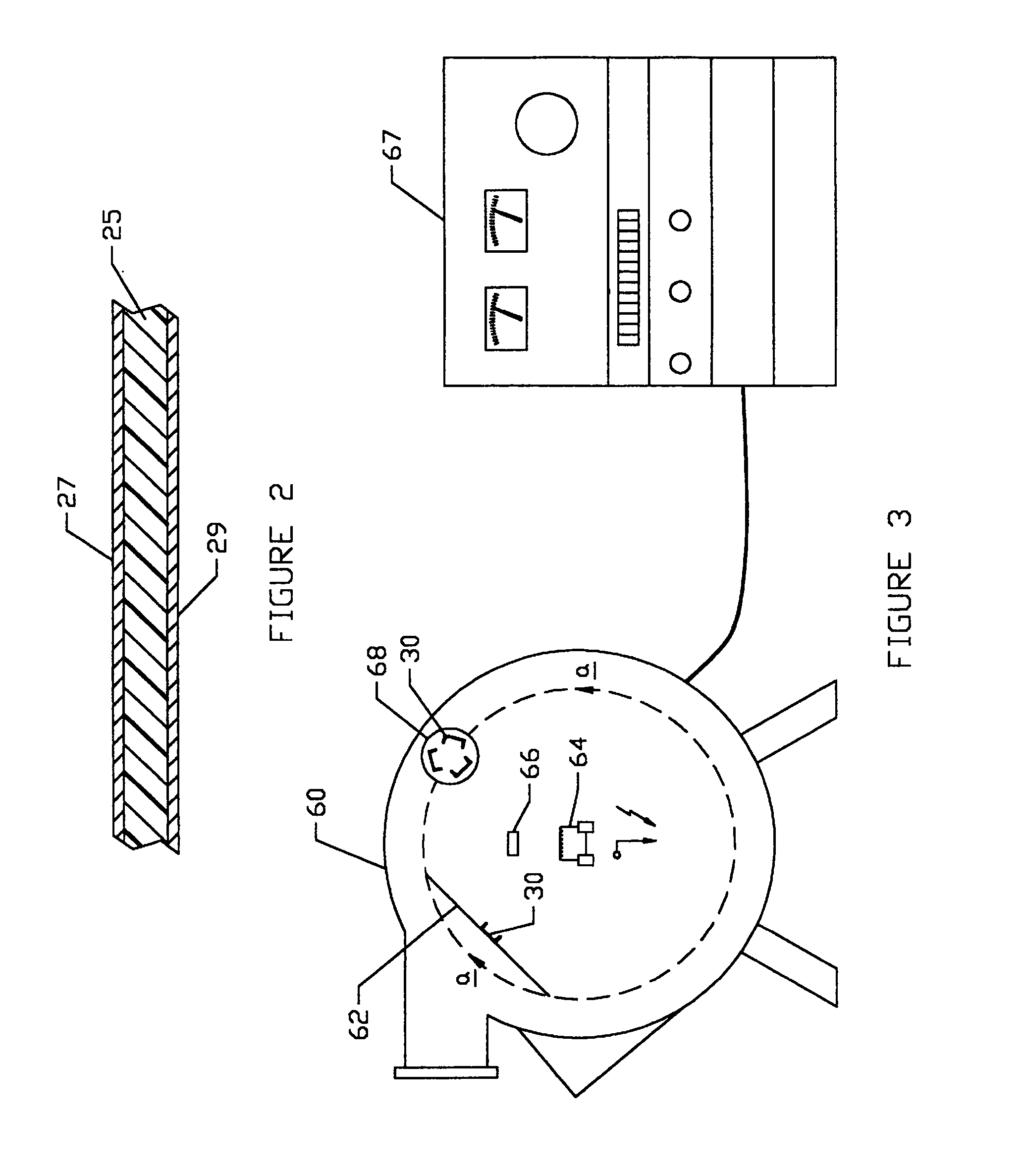
[0085] Eight samples were tested for shielding effectiveness using the “modified MIL-STD-285” method. In this procedure, samples to be tested are mounted in a test opening in the wall of shield room. The tests are run by radiating the test samples with a signal generator and antenna inside the room, and measuring the levels outside the shield room with a spectrum analyzer and antenna. A baseline measurement was made through the open hole, without any samples in place. The difference in these two measurements—before and after the samples are installed in the hole—yields the “shielding effectiveness.”

[0086] Certain errors can be introduced in this method at lower frequencies. The “hole” itself provides shielding when the longest dimension is less than one half wavelength, but since values are subtracted from the “baseline”, the errors give more conservative lower levels of shielding than free space measurements. In this case, these errors only affected the 30 and 50 MHz measurements, ...


PUM

PropertyMeasurementUnit
thicknessaaaaaaaaaa
thicknessaaaaaaaaaa
thicknessaaaaaaaaaa

Abstract

An EMI shield for personal computers, cellular telephones, and other electronic devices is constructed from thermoformable polymeric material which is then metallized on all surfaces by vacuum metallization techniques to provide an inexpensive, lightweight, yet effective EMI shield.

Description

CROSS-REFERENCES TO RELATED APPLICATIONS [0001] This application is a continuation of application Ser. No. 10 / 659,838, filed Sep. 10, 2003, which is a continuation of application Ser. No. 09 / 732,235, filed Dec. 7, 2000, now U.S. Pat. No. 6,624,353, which is a continuation of application Ser. No. 08 / 958,595, filed Oct. 29, 1997, now U.S. Pat. No. 6,570,085, which is a division of application Ser. No. 08 / 463,297, filed Jun. 5, 1995, now U.S. Pat. No. 5,811,050, which is a continuation-in-part of application Ser. No. 08 / 254,250, filed Jun. 6, 1994, now abandoned, the complete disclosures of which are incorporated herein by reference in their entirety for all purposes.BACKGROUND OF THE INVENTION [0002] This invention pertains to shielding apparatus for containing high frequency electromagnetic radiation within a personal computer, cellular telephone, or other electronic instrument. [0003] Electromagnetic compatibility (EMC) is a broad term used to describe electromagnetic interference (...

Claims


Application Information

Patent Timeline
Patent Type & Authority Applications(United States)
IPC IPC(8): H05K9/00B29C51/10C23C14/20G06F1/18
CPCB29C51/10B29C2791/001B29C2791/006B29K2995/0005H05K9/0084G06F1/182H05K9/0045H05K9/0073C23C14/20Y10T428/31678
Inventor GABOWER, JOHN F.
Owner WAVEZERO
Why Eureka
Try Eureka