Motor, Blower, Compressor, And Air Conditioner

a technology for compressors and motors, applied in the direction of magnetic circuit rotating parts, mechanical energy handling, magnetic circuit shape/form/construction, etc., can solve problems such as difficulties in thinning the motor

Inactive Publication Date: 2007-08-30
DAIKIN IND LTD
View PDF12 Cites 19 Cited by
  • Summary
  • Abstract
  • Description
  • Claims
  • Application Information

AI Technical Summary

Problems solved by technology

However, when a magnet for creating a field magnet and an armature winding face each other in an axial direction as described above, respective widths of the magne

Method used


Image

  • Motor, Blower, Compressor, And Air Conditioner
  • Motor, Blower, Compressor, And Air Conditioner
  • Motor, Blower, Compressor, And Air Conditioner

Examples


first embodiment

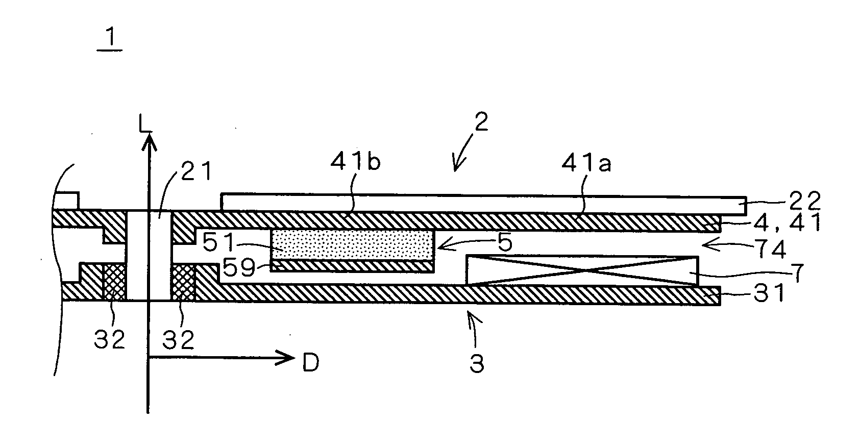
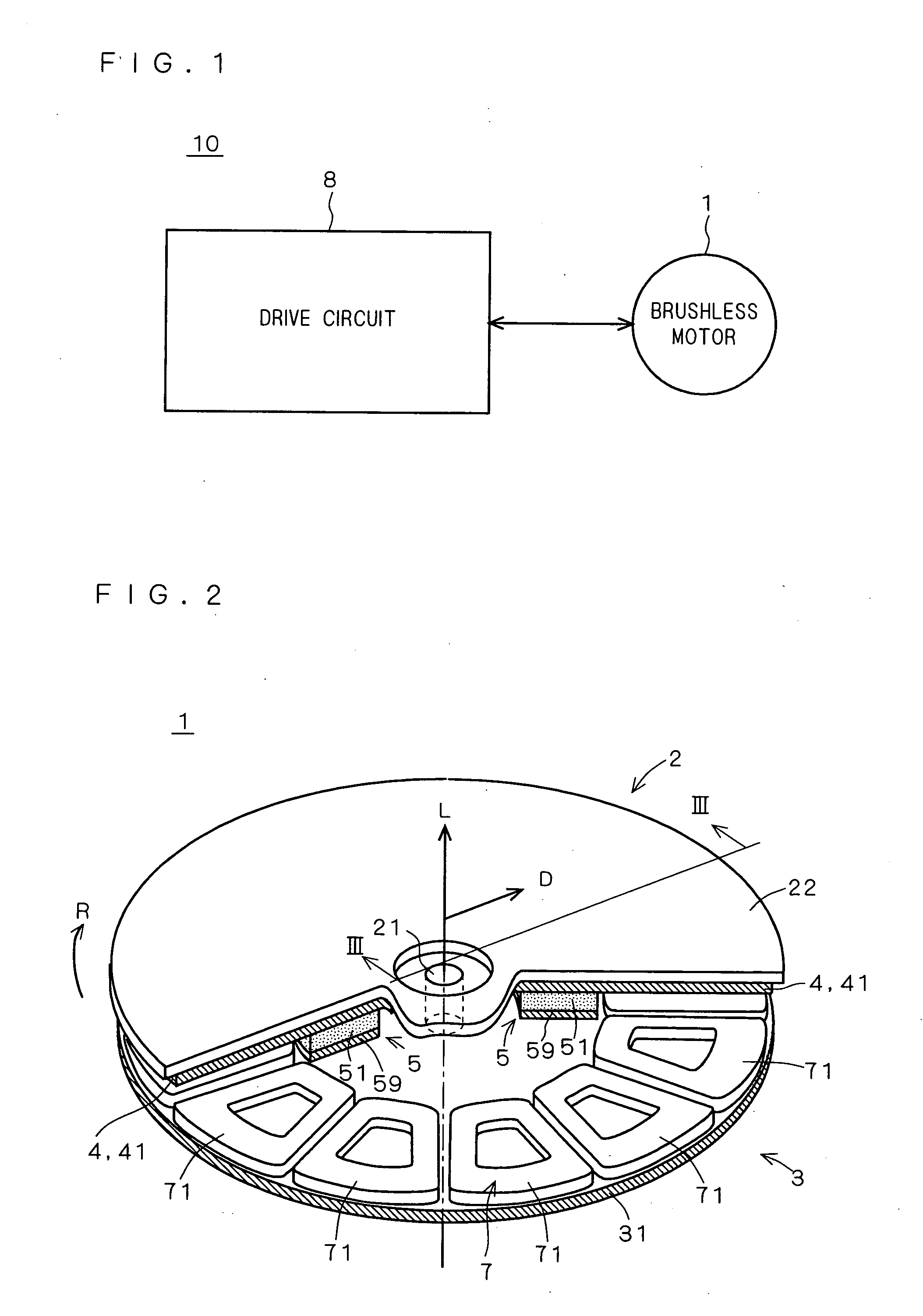
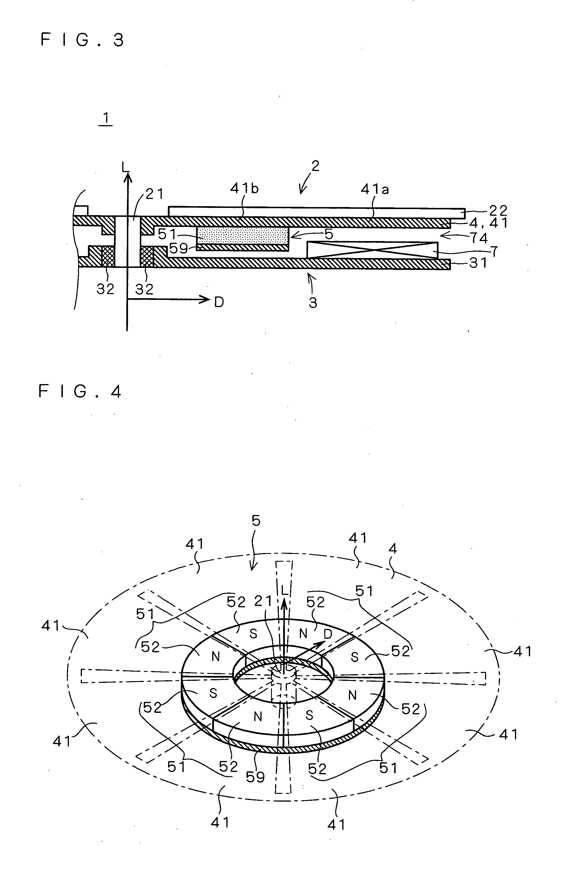
[0017] a motor according to the present invention includes an armature (3) and a field element (2) which are rotatable relative to each other on a rotation axis (21) extending in a first direction (L). The armature (3) includes an armature winding (7) which is placed at a distance in a second direction (D) perpendicular to the first direction (L) from the rotation axis (21). The field element (2) includes: a plurality of first yoke plates (41) each of which includes one end which faces the armature winding (7) in the first direction (L) and the other end which does not face the armature winding (7) in the first direction (L) and extends in the second direction (L); and a magnetic-field creating magnet (5) which has a north pole joined to the other end of one of adjacent first yoke plates (41) of the plurality of first yoke plates (41), a south pole joined to the other end of the other of the adjacent first yoke plates (41), and a U-shaped magnetic path (Φ1) which opens to the plural...

fourth embodiment

[0020] the motor according to the present invention is the first embodiment of the motor in which each of the plurality of first yoke plates (41) includes a linear outline (411) parallel to the second direction (D).

fifth embodiment

[0021] the motor according to the present invention is the first embodiment of the motor in which an interval (461) between the adjacent first yoke plates (41) increases as a distance from the rotation axis (21) increases in the second direction (D).


PUM


Abstract

It is an object of the present invention to provide techniques for improving efficiency and torque of a motor while achieving thinning of the motor. In a brushless DC motor, a rotor includes a magnetic-field creating magnet and a stator includes an armature winding. The magnetic-field creating magnet and the armature winding are placed to locally face in a radial direction orthogonal to an axial direction. This reduces a thickness of the brushless DC motor which extends in the axial direction. Also, a short-circuit yoke plate for joining and magnetically short-circuiting the north pole and the south pole of a permanent magnet is placed on a negative side in the axial direction with respect to the magnetic-field creating magnet. By provision of the short-circuit yoke plate, a magnetic path on a negative side in the axial direction with respect to the magnetic-field creating magnet can be shortened. Accordingly, magnetic reluctance occurring during rotational movement of the brushless DC motor can be reduced, to thereby improve efficiency and torque of the brushless DC motor.

Description

TECHNICAL FIELD [0001] The present invention relates to techniques for a motor including an armature and a field element which are rotatable relative to each other on a rotation axis. BACKGROUND ART [0002] A known example of a motor including an armature and a field element which are rotatable relative to each other on a rotation axis is an axial gap brushless DC motor (which will hereinafter be simply referred to as a “brushless motor”). In general, in an axial gap brushless motor, a rotor includes a magnetic-field creating magnet and a stator includes an armature winding and a yoke plate. Then, a structure in which the magnetic-field creating magnet and the armature winding face each other in an axial direction parallel to a rotation axis is employed. [0003] For the magnetic-field creating magnet of the rotor, a magnet which is plate-shaped and has magnetic poles which are arranged along a thickness thereof (orthogonal to a flat portion) and are different from each other in polari...

Claims


Application Information

Patent Timeline
IPC IPC(8): H02K21/12H02K1/22H02K1/12H02K1/27H02K7/14H02K21/24H02K29/08
CPCH02K21/24H02K7/14
Inventor YAMAGIWA, AKIO
Owner DAIKIN IND LTD
Why Eureka
Try Eureka