Display device

a technology of a display device and a display body, which is applied in the direction of discharge tubes, luminescnet screens, instruments, etc., can solve the problems of poor air tightness, high cost, and difficulty in handling the support body without damage, so as to suppress the occurrence of leakage and improve quality and reliability

Inactive Publication Date: 2007-08-30
KIJIMA YUUICHI +4
View PDF1 Cites 12 Cited by
  • Summary
  • Abstract
  • Description
  • Claims
  • Application Information

AI Technical Summary

Benefits of technology

[0027]The present invention was made to solve this problem. It is an object of the present invention to provide a display device which is improved in quality and reliability by suppressing the occurrence of leakage attributable to dislocations during the preliminary baking and during the panel sealing.
[0028]According to the present invention, to achieve the above object, a display device, in which a front substrate, a rear substrate and a support body are bonded so as to form a hermetically sealed space therein, is characterized in that the support body is formed of a plurality of constituent pieces by bonding them together and plural kinds of bonding materials exhibiting different softening temperatures are used to hermetically bond each constituent piece to the adjacent one. Since this configuration reduces the possibility of dislocation during the preliminary baking and during the panel sealing, it is possible to solve the problem of the related art.
[0029]According to one aspect of the present invention, there is provided a display device which comprises a first bonding material for bonding the central area of each constituent piece's bonding surface and a second bonding material for bonding the marginal area around the central area wherein the softening temperature of the first bonding material is higher than that of the second bonding material. Since this reduces the possibility of dislocation during the preliminary baking and during the panel sealing, it is possible to solve the problem of the related art.

Problems solved by technology

In the above-mentioned conventional art wherein two glass plates are bonded together via a single-piece support frame, it is difficult to handle the support body without damaging it if the display device (screen size) is large.
In addition, such a single-piece support frame is likely to waste more in blank cutout, resulting in a higher cost.
Thus, this pressure bonding may result in poor air-tightness of each junction, causing the occurrence of leak therefrom.
One of challenges in this technical field has been to eliminate the above drawback.
However, if the frit used to bond together the constituent pieces of the support body softens at the sealing temperature during the panel sealing, the constituent pieces may be dislocated when the frit is preliminarily baked and when the panel is sealed, resulting in the leakage.

Method used


Image

  • Display device
  • Display device
  • Display device

Examples


first embodiment

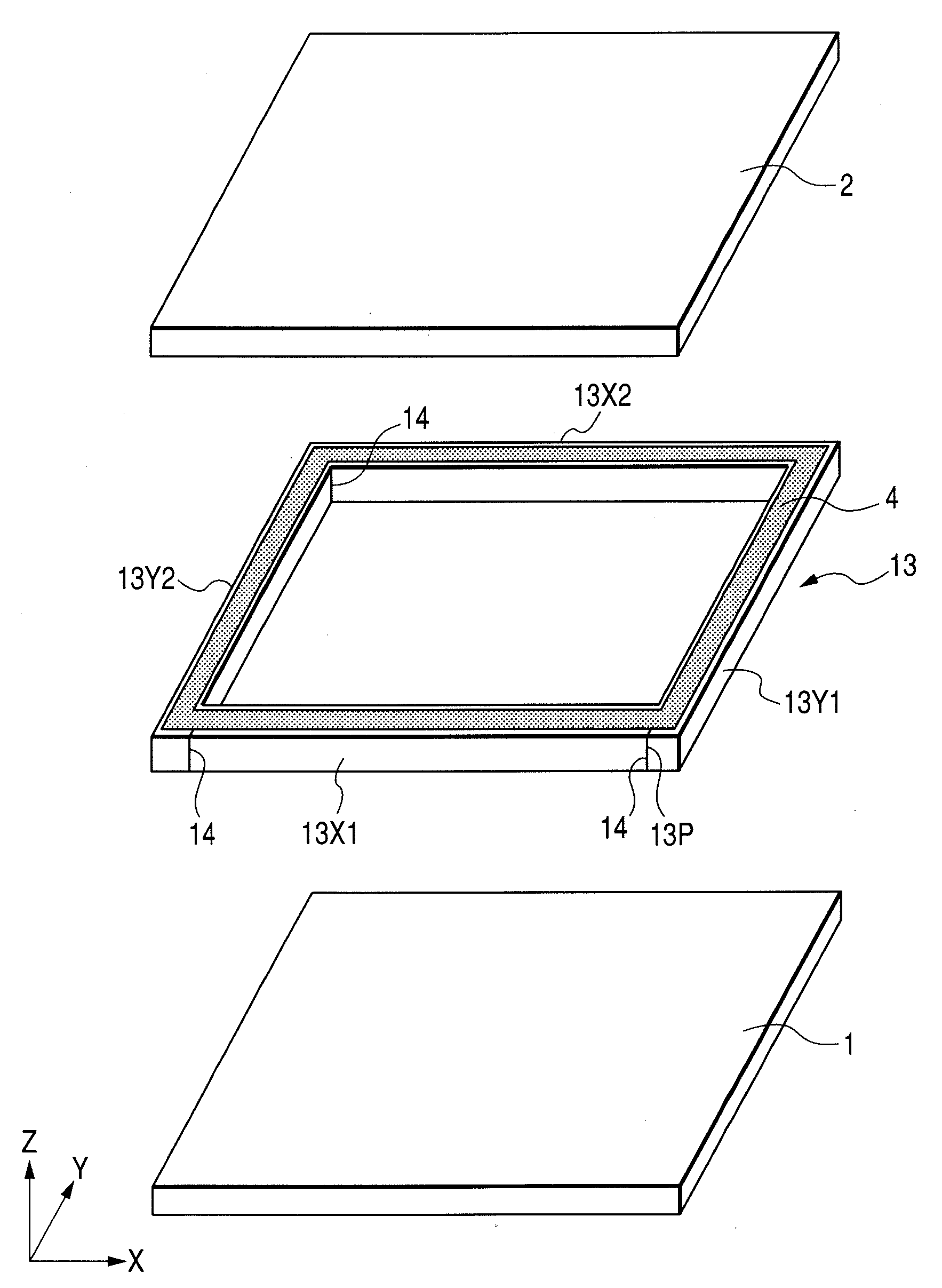
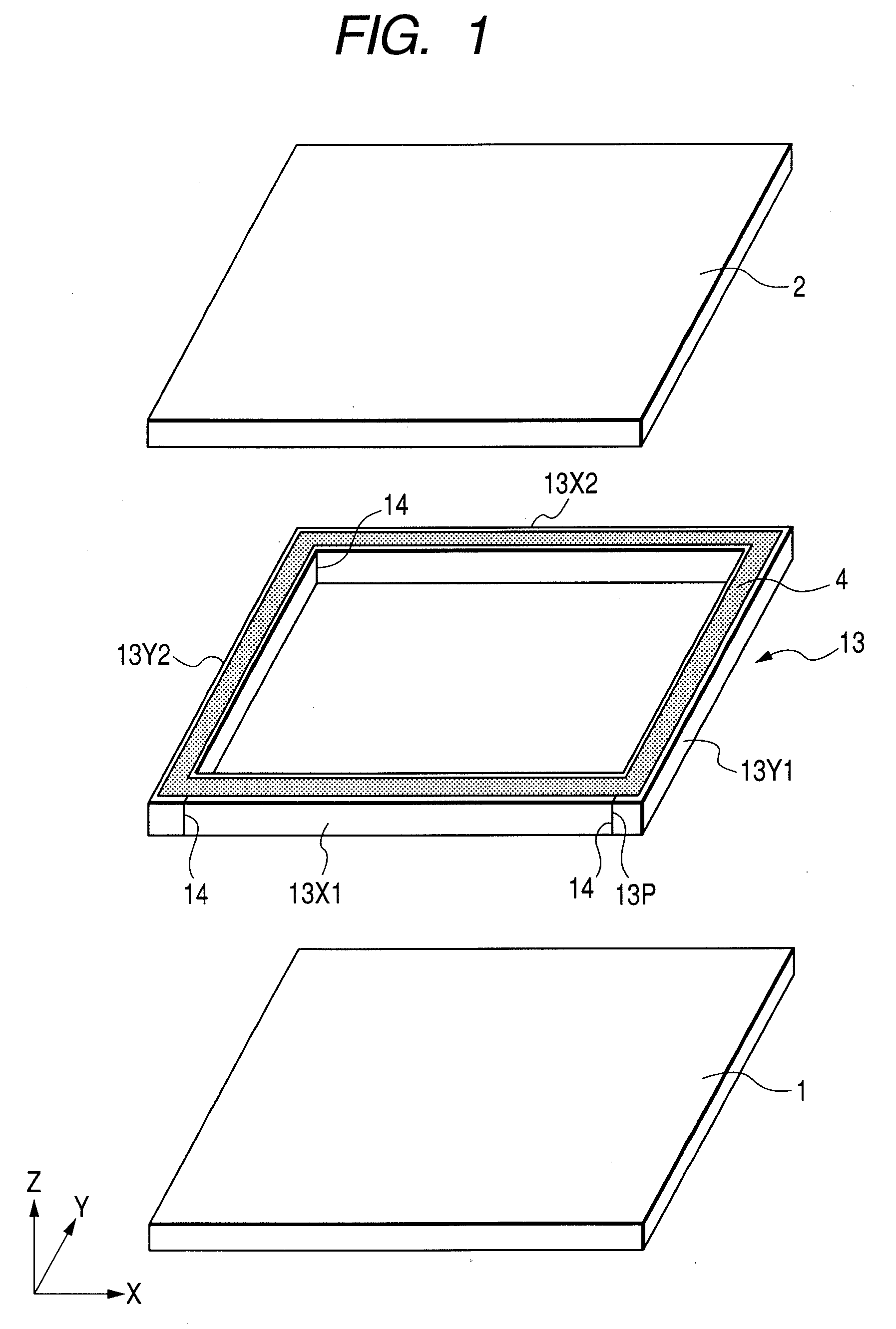
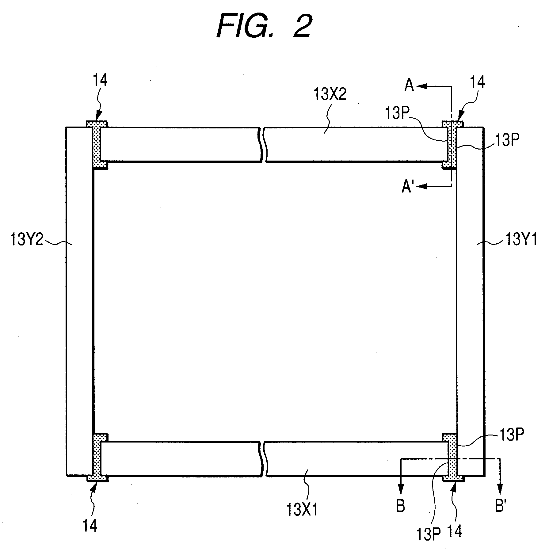
[0069]FIG. 1 is a developed perspective view of a display device according to a first embodiment of the present invention. Also, FIG. 1 schematically explains how a rear substrate, a front substrate and a support body are assembled. In the figure, the Z axis indicates the direction in which the front substrate 2 and the rear substrate 1 are stacked. FIG. 2 is an enlarged cross-sectional view of the support body shown in FIG. 1. FIG. 3 shows a junction between constituent pieces of the support body. FIG. 3A is an enlarged cross-sectional view taken along line A-A′ of FIG. 2. Likewise, FIG. 3B is an enlarged sectional view taken along line B-B′ of FIG. 2.

[0070]In this display device, the rear substrate 1 and the front substrate 2 are formed of a glass plate and the support body 13 is made of a glass material. Here, various components such as electron sources, phosphor layers and the like which are formed on respective inner surfaces of the rear substrate 1 and the front substrate 2 ar...

second embodiment

[0087]FIG. 7 is an enlarged sectional view for explaining a display device according to a second embodiment of the present invention. FIG. 7 shows a junction taken along line A-A′ indicated in FIG. 2. Each part is given the same reference numeral as the corresponding one in the aforementioned figures and its description is omitted here if the part is identical to the corresponding one. FIG. 7 is different from FIG. 3A in that, for the bonding members 14, the first bonding member 141 is applied to a central transverse area of each bonding surface 13P in the longitudinal direction of each bonding surface 13P while the second bonding member 142 whose softening temperature is lower than that of the first bonding member 141 is applied to the remaining upper and lower areas of the first bonding member 141. The support body members 13X1, 13X2, 13Y1 and 13Y2, not shown in the figure, are hermetically bonded together via their respective bonding surfaces 13P.

[0088]Also in this construction, ...

third embodiment

[0090]FIG. 8 is an enlarged top sectional view of a support frame for explaining a display device according to a third embodiment of the present invention. Each part is given the same reference numeral as the corresponding one in the aforementioned figures and its description is omitted here if the part is identical to the corresponding one. FIG. 8 is different from FIG. 2 in that two long-side support body members 13X1, 13X2 and two short-side support body members 13Y1, 13Y2, which are combined to form a support body 13 have different widths.

[0091]That is, width WX of the two long-side support body members 13X1 and 13X2 is larger than width WY of the two short-side support body members 13Y1 and 13Y2 (WX>WY). The two long-side support body members 13X1 and 13X2 are sandwiched between the two short-side support body members 13Y1 and 13Y2 via bonding members 14 which are structured as described above with FIG. 3A or FIG. 7.

[0092]In this construction, the two long-side support body mem...


PUM


Abstract

The present invention provides a display device allowing the quality and reliability to be improved by preventing the occurrence of vacuum leak attributable to dislocation which may be caused by preliminary baking and panel sealing.A display device in which the end surfaces of a support body 13 are hermetically bonded to a front substrate 2 and a rear substrate 1 by sealing members 4. In the display device, the support body 13 is formed by bonding together a plurality of support body members 13X1, 13X2, 13Y1 and 13Y2, and adjacent support body members are bonded by using a first bonding member 141 for bonding a central area of each bonding surface and a second bonding member 142 for bonding a marginal area around the central area. The softening temperature of the first bonding member is set higher than the softening temperature of the second bonding member.

Description

CLAIM OF PRIORITY[0001]The present application claims priority from Japanese Application JP 2006-053021 filed on Feb. 28, 2006, the content of which is hereby incorporated by reference into this application.BACKGROUND OF THE INVENTION[0002]1. Field of the Invention[0003]The present invention relates to a display device and particularly to a display device provided with a support body which is interposed between substrates so as to surround a sealed space formed between the substrates. More particularly, the invention relates to a bonding structure of a plurality of support body members forming the support body.[0004]2. Description of the Related Art[0005]For display devices which exhibit excellent properties such as high brightness and high definition, color cathode ray tubes have been widely used. Recently, along with the improvement of image quality of information processing devices and television broadcasting, there has been a demand for flat plate displays (panel displays) which...

Claims


Application Information

Patent Timeline
Patent Type & Authority Applications(United States)
IPC IPC(8): H01J1/62H01J63/04H01J21/10
CPCH01J11/10H01J11/48H01J2329/8675H01J2329/862H01J29/862
Inventor KIJIMA, YUUICHIOROKU, NORIYUKIHIRASAWA, SHIGEMITACHIHARA, HIROYUKIYAMABA, IKUO
Owner KIJIMA YUUICHI
Why Eureka
Try Eureka