
Electrochemical cell structure and method of fabrication

Inactive Publication Date: 2007-08-30
SEIKO EPSON CORP
View PDF14 Cites 13 Cited by
  • Summary
  • Abstract
  • Description
  • Claims
  • Application Information

AI Technical Summary

Benefits of technology

[0022] The present invention aims to address the above mentioned problems of manufacturing electrochemical cells (DSSC's and ECD's) of the prior art, to improve the efficiency with which they are made and thus further decrease their fabrication costs.
[0035] The method of fabrication of the electrochemical cell of the present invention, using inkjet printing, is advantageous over screen printing fabrication as format scaling (up or down) does not require re-investment in machine hardware. This is because inkjet fabrication is software controlled and the software can be reconfigured without the expense of commissioning new screens. Additionally, inkjet heads are significantly more durable, than patterned screens, as patterned screens last only approximately 100 uses.
[0036] Furthermore, the drop on demand placement enabled by inkjet fabrication is less wasteful than screen printing. Unlike conventional inkjet overwriting, where each deposited layer is dried and then printed over to produce a thick deposition, the inkjet flood filling technique, which doses a confined region with a large volume of liquid to provide the required deposit thickness, has been shown to produce fracture-free metal oxide layers. Moreover, the surface confinement used to enable flood filling, through the use of a bank structure, ensures long range uniform material distribution and therefore uniform and repeatable performance. Additionally, surface confinement through the use of a bank structure ensures enhanced picture quality and contrast by colour separation between the different coloured cells.

Problems solved by technology

While advanced silicon based solar cells are now widely commercially available, their uptake has been slow due to high production costs, a lack of robustness and associated visual pollution resulting from the large surface exposure requirements.
However, DSSC's are less efficient than crystalline solar cells.
A single electrochromic molecular monolayer on a planar substrate would not absorb sufficient light to provide a strong colour contrast between the bleached and unbleached states.
However, metal oxide layer fabrication using screen-printing often results in a ±5% film thickness variation caused by residual blocked or dirty screen cells, adhesion to the screen during separation from the substrate surface and trapped bubble expansion during drying, caused by the inability to completely outgas a viscous paste.
Other methods, such as doctor-blading, also suffer from an inability to provide a well defined thick metal oxide layer without significant spatial deviations.
Subsequent porosity and film quality deviations are therefore likely to occur throughout such metal oxide layers, resulting in a degradation of efficiency and image quality for the DSSC and ECD, respectively.
As a result, fabrication of an electrochemical device based on a functionally sensitised thick porous metal oxide layer, as for the DSSC and ECD, using the aforementioned fabrication techniques are inappropriate from the view points of device reproducibility and adaptability to large size device production.

Method used


Image

  • Electrochemical cell structure and method of fabrication
  • Electrochemical cell structure and method of fabrication
  • Electrochemical cell structure and method of fabrication

Examples


Embodiment Construction

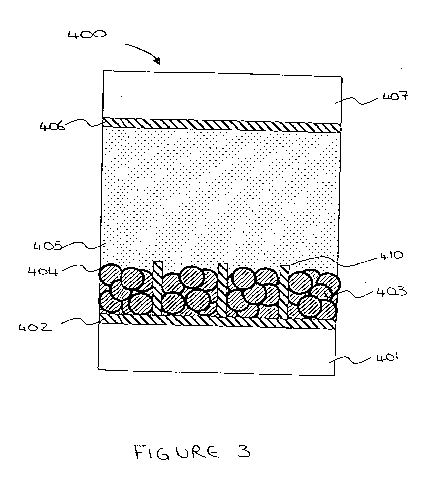
[0043] The present invention relates to an electrochemical cell such as a Dye Sensitised Solar Cell (DSSC) or an electrochromic display (ECD). One electrochemical cell 400 of the present invention comprises, with reference to FIG. 3, a first transparent insulating substrate layer 401; a first transparent conductive oxide (TCO) electrode layer 402; a metal oxide layer 403; a sensitiser (dye) / electrochromic material layer 404; an electrolyte layer 405; a second TCO electrode layer 406; and a second transparent insulating substrate layer 407.

[0044] The first and second transparent insulating substrate layers 401, 407 are preferably glass or plastic. The metal oxide layer 403 is preferably titanium dioxide (TiO2) and is a semiconductor.

[0045] The metal oxide layer 403 should preferably be a material which promotes intimate adhesion of the sensitiser (dye) / electrochromic material layer 404 on its surface. Additionally, the particles of the metal oxide layer 403 must be reasonably light...


PUM

PropertyMeasurementUnit
Fractionaaaaaaaaaa
Diameteraaaaaaaaaa
Diameteraaaaaaaaaa

Abstract

An electrochemical cell and a method of manufacturing the same are provided. The electrochemical cell comprising: a first conductive layer; a metal oxide layer formed on the first conductive layer, the metal oxide layer comprising a plurality of adjacent metal oxide cells, spaced from one another; a functional dye layer formed on the metal oxide layer; a second conductive layer; and an electrolyte between the functional dye layer and the second conductive layer, wherein at least one of the first and second conductive layers is transparent, and wherein the metal oxide layer is formed from a metal oxide particle dispersion liquid.

Description

FIELD OF THE INVENTION [0001] The present invention relates to an electrochemical cell structure and a method of fabrication. In particular, the present invention relates to a metal oxide particles dispersion liquid used in the formation of a metal oxide layer. BACKGROUND OF THE INVENTION [0002] The International Energy Agency's “World Energy Outlook” predicts that global primary energy demand will increase by 1.7% per year from 2000 to 2030. It also predicts that 90% of this demand will be met by fossil fuels. Consequently, there will be a 1.8% per year increase in carbon dioxide from 2000 to 2030, reaching 38 billion tonnes in 2030. Cleaner, renewable energy sources, including solar cells, have long been heralded as counters to this increased pollution trend. While advanced silicon based solar cells are now widely commercially available, their uptake has been slow due to high production costs, a lack of robustness and associated visual pollution resulting from the large surface ex...

Claims


Application Information

Patent Timeline
IPC IPC(8): H01G9/00G02F1/1506
CPCB82Y20/00Y10T29/49002G02F1/1533G02F2202/04G02F2202/36H01G9/2031H01G9/2081H01L51/0005Y02E10/542H01L31/022425H01L31/022466H01L31/02366H01G9/2027H01G9/2059G02F1/1506Y02P70/50H10K71/135H01G9/2068
Inventor MCGREGOR, BARRYISHIDA, MASAYA
Owner SEIKO EPSON CORP
Learn More