Fluid mixing system
- Summary
- Abstract
- Description
- Claims
- Application Information
AI Technical Summary
Benefits of technology
Problems solved by technology
Method used
Image
Examples
first embodiment
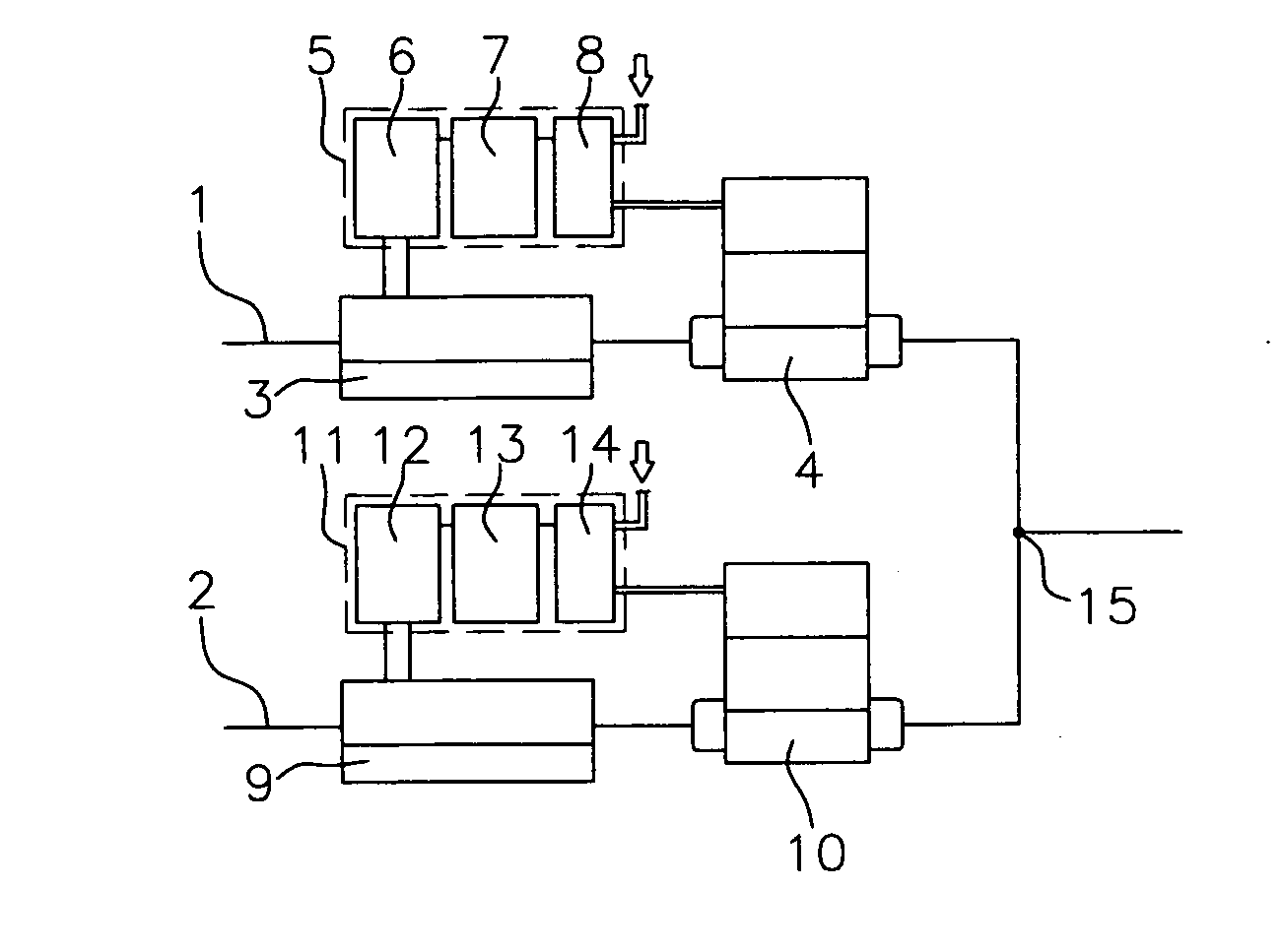
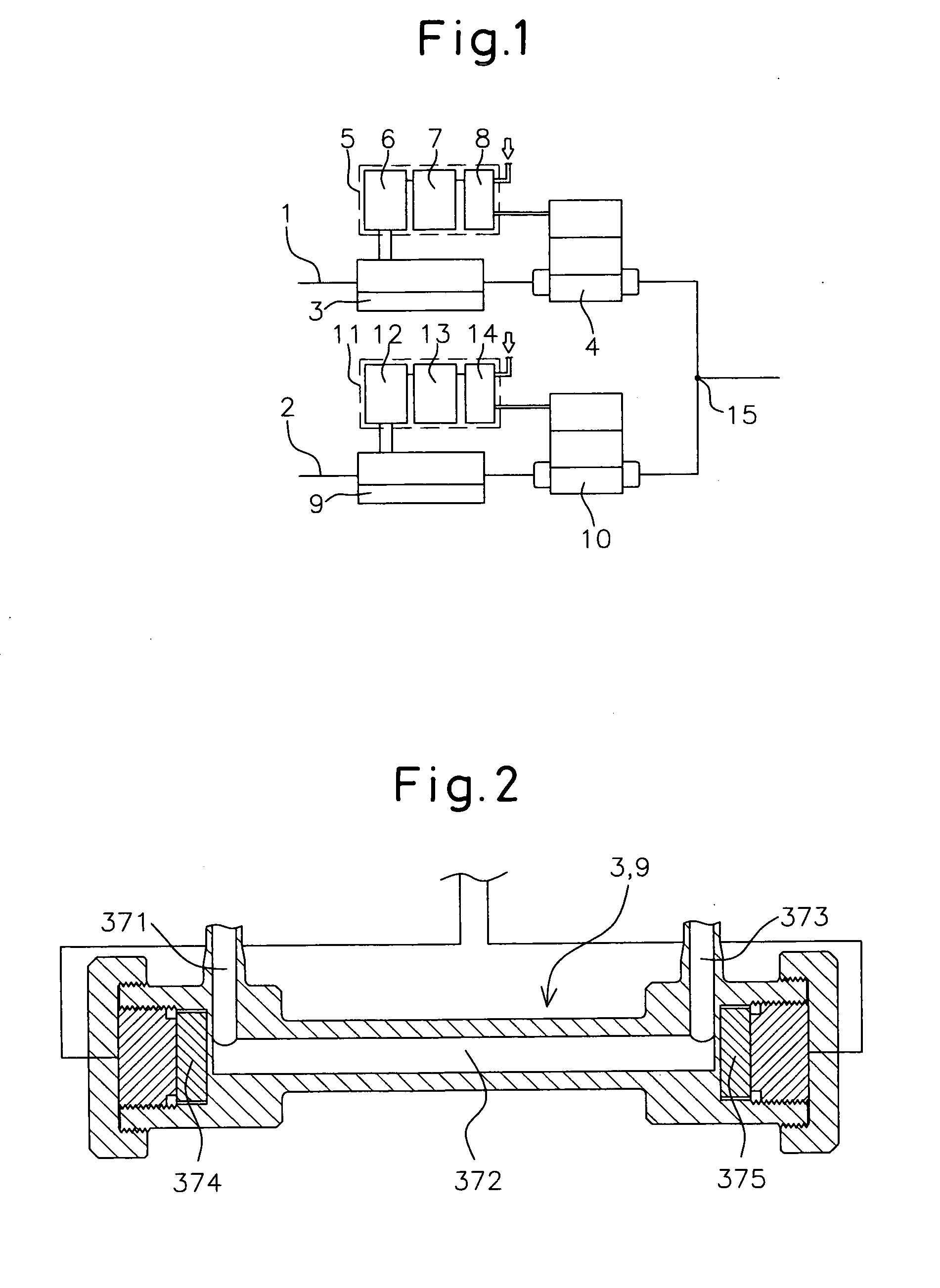
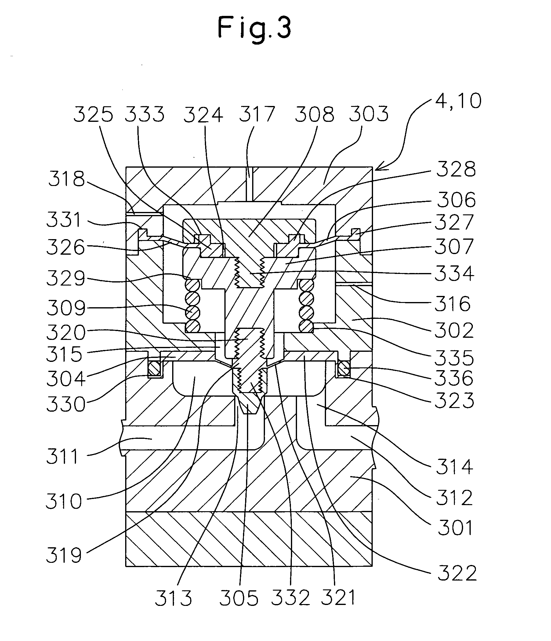
[0076]Below, a fluid mixing system of a first embodiment of the present invention will be explained based on FIG. 1 to FIG. 3.
[0077]This fluid mixing system is formed from two feed lines, that is, a first feed line 1 and a second feed line 2. The first feed line 1 has a flow rate measuring device 3 and a fluid control valve 4 connected to it in that order and is provided with a control unit 5, while the second feed line 2 has a flow rate measuring device 9 and fluid control valve 10 connected to it in that order and is provided with a control unit 11. At the downstream-most sides of the first and second feed lines 1, 2, a header 15 of the feed lines 1, 2 is provided. The configurations of these components will be explained below.
[0078]3, 9 are flow rate measuring devices constituted as ultrasonic flow meters for measuring the flow rates of the fluids. Each of the flow rate measuring devices 3, 9 has an inlet channel 371, a straight channel 372 provided perpendicularly from the inlet...
second embodiment
[0103]Next, a fluid mixing system of a second embodiment of the present invention will be explained based on FIG. 4 and FIG. 5.
[0104]This fluid mixing system is formed from two feed lines, that is, a first feed line 16 and a second feed line 17. The first feed line 16 has a shutoff valve 18, a flow rate measuring device 19, and a fluid control valve 20 connected to it in that order and is provided with a control unit 21, while the second feed line 17 has a shutoff valve 22, a flow rate measuring device 23, and a fluid control valve 24 connected to it in that order and is provided with a control unit 25. At the downstream-most sides of the first and second feed lines 16, 17, a header 26 of the feed lines 16, 17 is provided. The configurations of these components will be explained below.
[0105]18, 22 are shutoff valves. Each of the shutoff valves 18, 22 is formed by a body 101, drive unit 102, piston 103, diaphragm holder 104, and valve element 105.
[0106]101 is a PTFE body. This has a ...
third embodiment
[0114]Next, a fluid mixing system of a third embodiment of the present invention will be explained based on FIG. 6 and FIG. 7.
[0115]This fluid mixing system is formed from two feed lines, that is, a first feed line 27 and a second feed line 28. The first feed line 27 has a shutoff valve 29, a pressure regulating valve 30, a flow rate measuring device 31, and a fluid control valve 32 connected to it in that order and is provided with a control unit 33, while the second feed line 28 has a shutoff valve 34, a pressure regulating valve 35, a flow rate measuring device 36, and a fluid control valve 37 connected to it in that order and is provided with a control unit 39. At the downstream-most sides of the first and second feed lines 27, 28, a header 39 of the feed lines 27, 29 is provided. The configurations of these components will be explained below.
[0116]30, 35 are pressure regulating valves for controlling the fluid pressures in accordance with the operating pressures. Each of the pr...
PUM
| Property | Measurement | Unit |
|---|---|---|
| Fraction | aaaaa | aaaaa |
| Flow rate | aaaaa | aaaaa |
| Ratio | aaaaa | aaaaa |
Abstract
Description
Claims
Application Information
 - R&D
- Intellectual Property
- Life Sciences
- Materials
- Tech Scout
- Unparalleled Data Quality
- Higher Quality Content
- 60% Fewer Hallucinations
Browse by: Latest US Patents, China's latest patents, Technical Efficacy Thesaurus, Application Domain, Technology Topic, Popular Technical Reports.
© 2025 PatSnap. All rights reserved.Legal|Privacy policy|Modern Slavery Act Transparency Statement|Sitemap|About US| Contact US: help@patsnap.com


