This helps you quickly interpret patents by identifying the three key elements:
Problems solved by technology
Method used
Benefits of technology
Benefits of technology
[0006]The present invention was made in consideration of the above problems in the prior art and has as its object the provision of a fluid mixing system able to control the flow rates of different lines of fluids to mix the fluids by any ratio, able to control the flow rates without problem even if pulsating fluids flow, compact in configuration, able to be installed in a narrow space, and enabling easy pipe laying and pipe connection at the time of installation.
Problems solved by technology
The individual fluid inflow systems 601 were not independently controlled, so control was not possible to mix any two or more fluids by any ratio.
Further, when pulsating fluids flowed through the fluid inflow systems 601, there was the problem that stable fluid control was no longer possible.
Further, the range of flow rates covered could not be made that large in this configuration, so there was the problem that the system was difficult to use for applications controlling a wide range of flow rates.
Further, since the control system had a large number of components, the control system itself became large and there was the problem of installation space.
The work was complicated and took time and the piping laying and cable laying work were troublesome, so there was the problem of a likelihood of error.
Method used
Image
Click on the blue label to locate the original text in one second.
Reading with bidirectional positioning of images and text.
Examples
first embodiment
[0077]Below, a fluid mixing system of a first embodiment of the present invention will be explained based on FIG. 1 to FIG. 3.
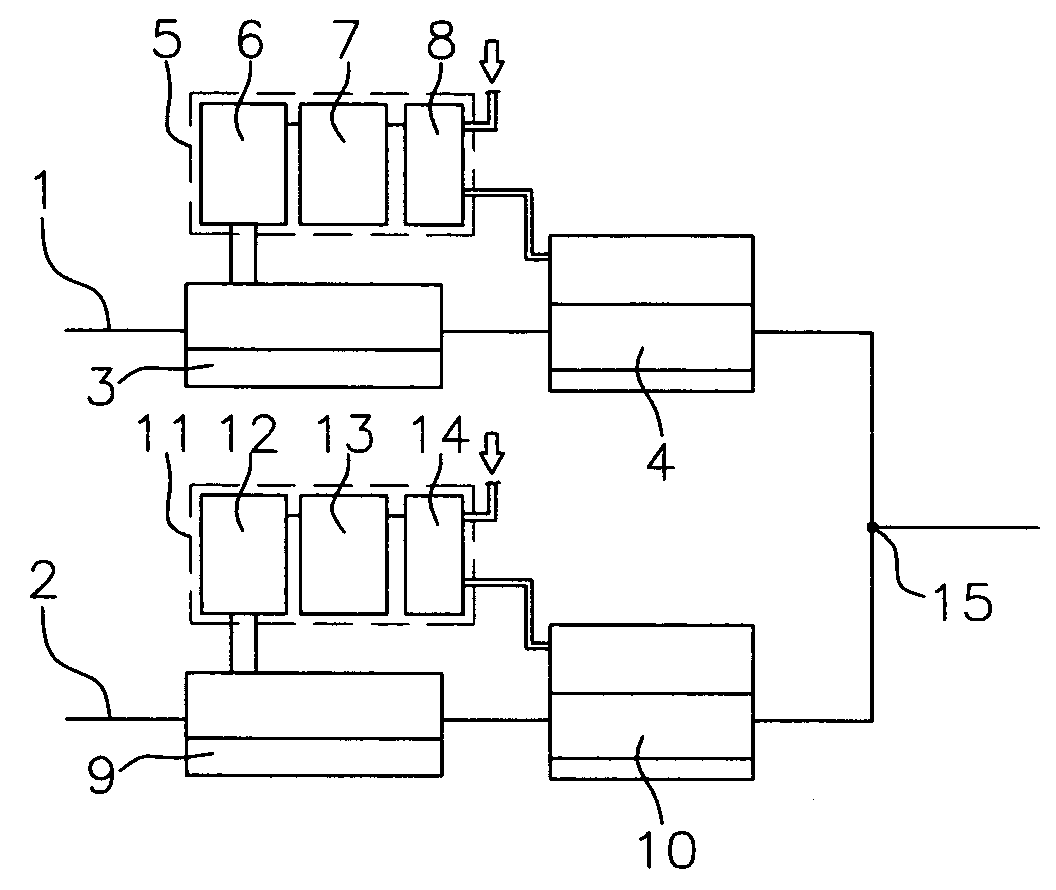
[0078]This fluid mixing system is formed from two feed lines, that is, a first feed line 1 and a second feed line 2. The first feed line 1 has a flow rate measuring device 3 and a fluid control valve 4 connected to it in that order and is provided with a control unit 5, while the second feed line 2 has a flow rate measuring device 9 and fluid control valve 10 connected to it in that order and is provided with a control unit 11. At the downstream-most sides of the first and second feed lines 1, 2, a header 15 of the feed lines 1, 2 is provided. The configurations of these components will be explained below.
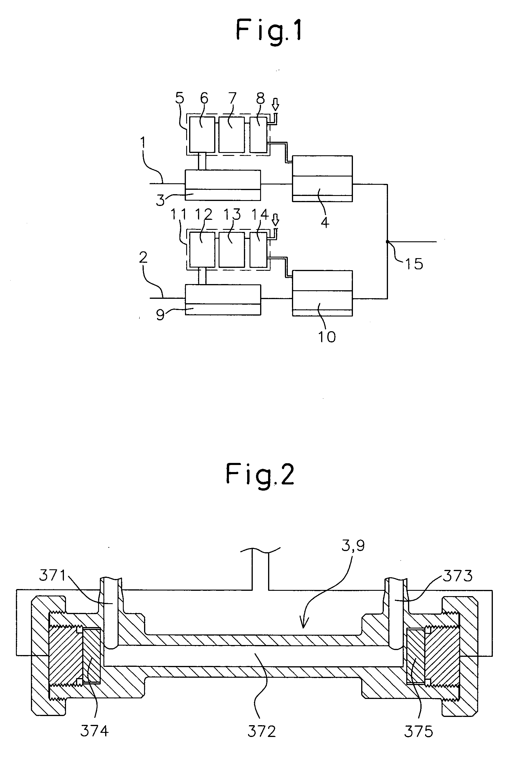
[0079]3, 9 are flow rate measuring devices constituted as ultrasonic flow meters for measuring the flow rates of the fluids. Each of the flow rate measuring devices 3, 9 has an inlet channel 371, a straight channel 372 provided perpendicularly from the inlet...
second embodiment
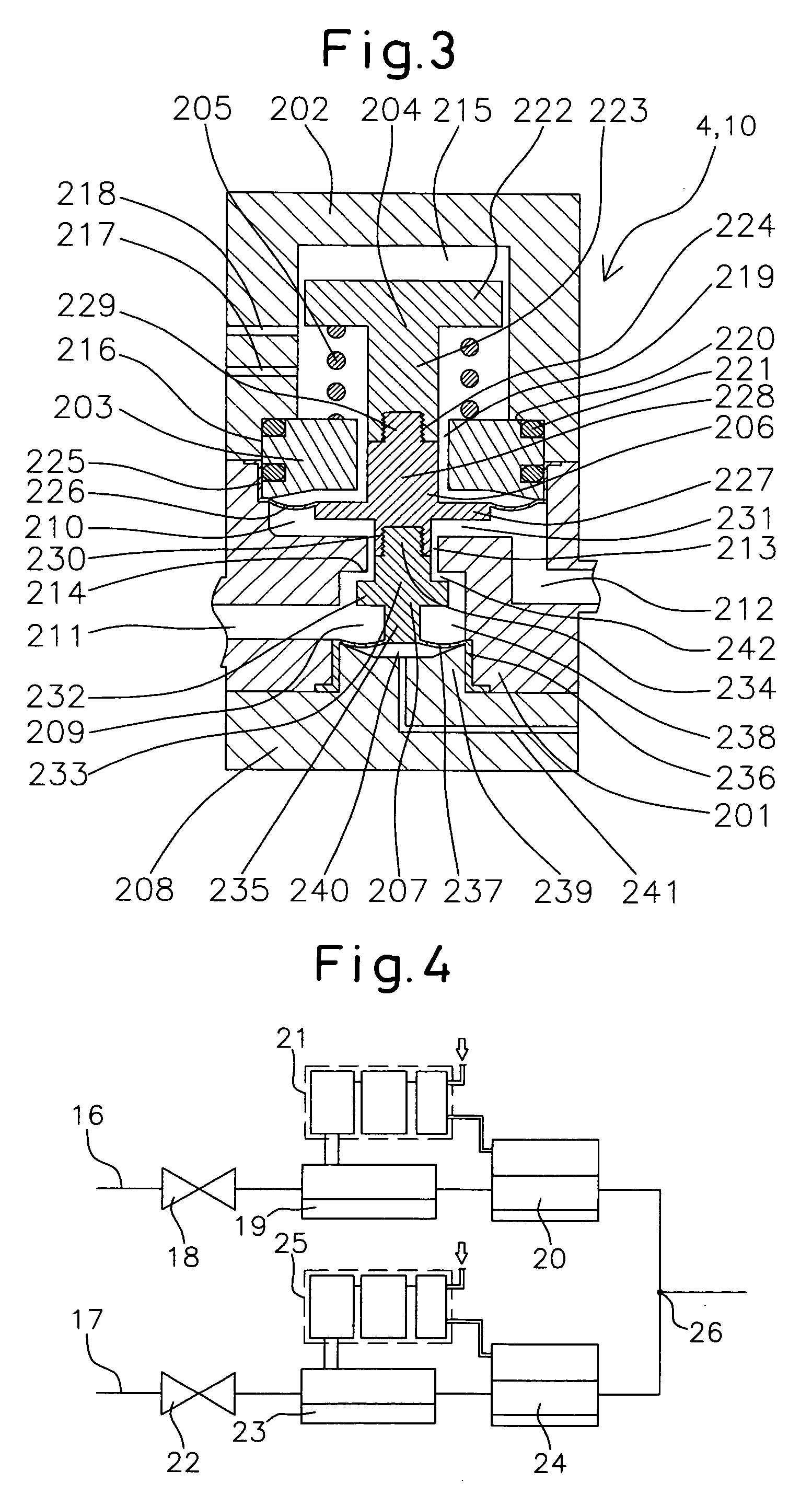
[0103]Next, a fluid mixing system of a second embodiment of the present invention will be explained based on FIG. 4 and FIG. 5.
[0104]This fluid mixing system is formed from two feed lines, that is, a first feed line 16 and a second feed line 17. The first feed line 16 has a shutoff valve 18, a flow rate measuring device 19, and a fluid control valve 20 connected to it in that order and is provided with a control unit 21, while the second feed line 17 has a shutoff valve 22, a flow rate measuring device 23, and a fluid control valve 24 connected to it in that order and is provided with a control unit 25. At the downstream-most sides of the first and second feed lines 16, 17, a header 26 of the feed lines 16, 17 is provided. The configurations of these components will be explained below.
[0105]18, 22 are shutoff valves. Each of the shutoff valves 18, 22 is formed by a body 101, drive unit 102, piston 103, diaphragm holder 104, and valve element 105.
[0106]101 is a PTFE body. This has a ...
third embodiment
[0115]Next, a fluid mixing system of a third embodiment of the present invention will be explained based on FIG. 6 to FIG. 10.
[0116]This fluid mixing system is formed from two feed lines, that is, a first feed line 27 and a second feed line 28. The first feed line 27 has a shutoff valve 29, a flow rate measuring device 30, a fluid control valve 31, and a throttle valve 32 in that order and is provided with a control unit 33, while the second feed line 28 has a shutoff valve 34, a flow rate measuring device 35, a fluid control valve 36, and a throttle valve 37 connected to it in that order and is provided with a control unit 38. At the downstream-most sides of the first and second feed lines 27, 28, a header 39 of the feed lines 27, 28 is provided. The configurations of these components will be explained below.
[0117]32, 37 are throttle valves able to adjust the opening areas. Each throttle valve is formed by a body 251, diaphragm 260, second stem 269, diaphragm holder 271, first stem...
PUM
Abstract
An object of the present invention is to provide a fluid mixing system able to mix the fluids of different lines by any ratio and control the flow rates of even pulsating fluids, able to control the flow rate of even a pulsating fluid, compact in configuration and able to be installed in a narrow space, and enabling easy pipe laying and pipe connection at the time of installation.In the system of the present invention, the feed lines 1, 2 are provided with fluid control valves 4, 10 controlling pressures of fluids by pressure operations of control fluids, flow rate measuring devices 3, 9 measuring actual flow rates of the fluids, converting the measured values of the actual flow rates to electrical signals, and outputting the same, and control units 5, 11 outputting command signals for controlling the opening areas of the fluid control valves to the fluid control valves or equipment operating the fluid control valves based on the errors between the measured values of the actual flow rates and flow rate settings. In the system of the present invention, for example, to obtain a washing solution for semiconductor production, hydrofluoric acid or hydrochloric acid is mixed with pure water by a ratio of 1 part to 10 to 200 parts.
Description
TECHNICAL FIELD[0001]The present invention relates to a fluid mixing system used for fluid transport pipes in which two or more of lines of fluid are mixed by any ratio. More particularly, it relates to a fluid mixing system able to control the flow rates of different lines of fluids to mix the fluids by any ratio, able to control the flow rates without problem even if pulsating fluids flow, compact in configuration, able to be installed in a narrow space, and enabling easy pipe laying and pipe connection at the time of installation.BACKGROUND ART[0002]In the past, as one step in the semiconductor production process, washing water comprised of fluoric acid or another chemical diluted with pure water has been used for etching the wafer surface, i.e., wet etching. It was considered that the concentration of the washing water for this wet etching had to be controlled with a high precision. In recent years, control of the concentration of the washing water by the ratio of the flow rates...
Claims
Application Information
Patent Timeline
Application Date:The date an application was filed.
Publication Date:The date a patent or application was officially published.
First Publication Date:The earliest publication date of a patent with the same application number.
Issue Date:Publication date of the patent grant document.
PCT Entry Date:The Entry date of PCT National Phase.
Estimated Expiry Date:The statutory expiry date of a patent right according to the Patent Law, and it is the longest term of protection that the patent right can achieve without the termination of the patent right due to other reasons(Term extension factor has been taken into account ).
Invalid Date:Actual expiry date is based on effective date or publication date of legal transaction data of invalid patent.

