Method and microscope for high spatial resolution examination of samples

a high spatial resolution, microscope technology, applied in the field of methods and microscopes, can solve the problems of limited imaging rate, achieve the effect of facilitating operability, high user friendliness, and maintaining stability

Active Publication Date: 2007-09-06
LEICA MICROSYSTEMS CMS GMBH
View PDF5 Cites 38 Cited by
  • Summary
  • Abstract
  • Description
  • Claims
  • Application Information

AI Technical Summary

Benefits of technology

[0027]A modular design of the microscope can be provided with regard to a high level of user friendliness, so that individual components and/or modules can easily be exchanged. Moreover, with regard to the ability to handle with particular ease it can be provided that individual components and/or subassemblies and/or the overall structure are mounted in a housing. In order to facilitate the operability, the o

Problems solved by technology

It is disadvantageous in the known methods that the structure of the light distribution in the

Method used


Image

  • Method and microscope for high spatial resolution examination of samples
  • Method and microscope for high spatial resolution examination of samples
  • Method and microscope for high spatial resolution examination of samples

Examples


Embodiment Construction

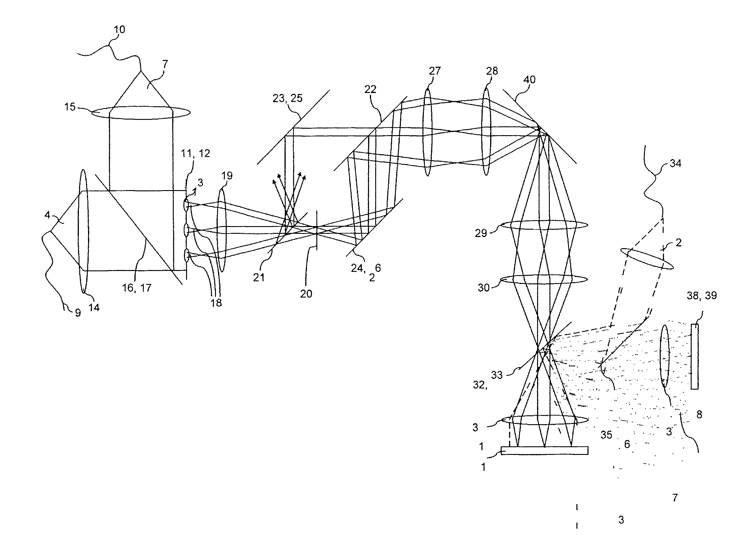
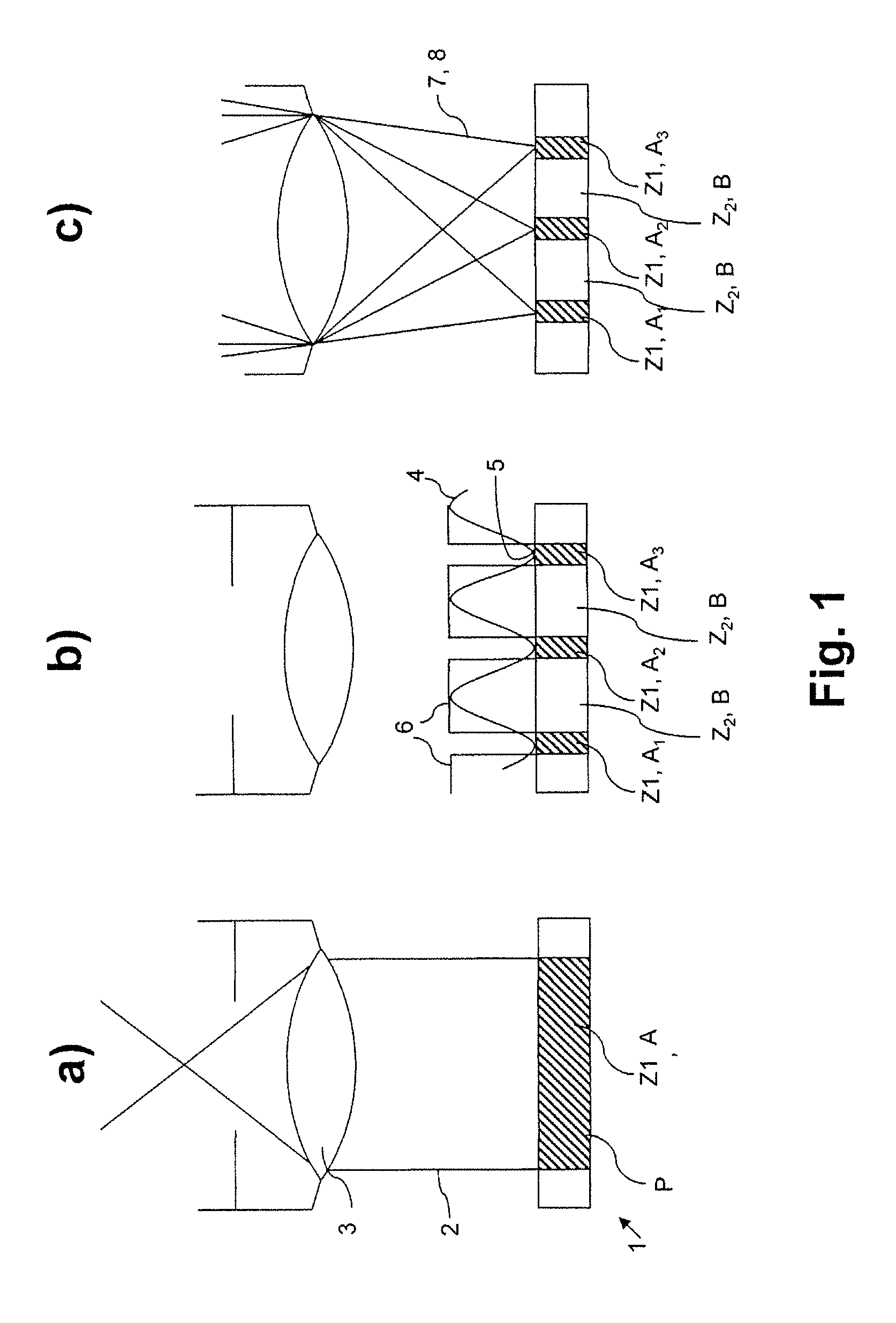
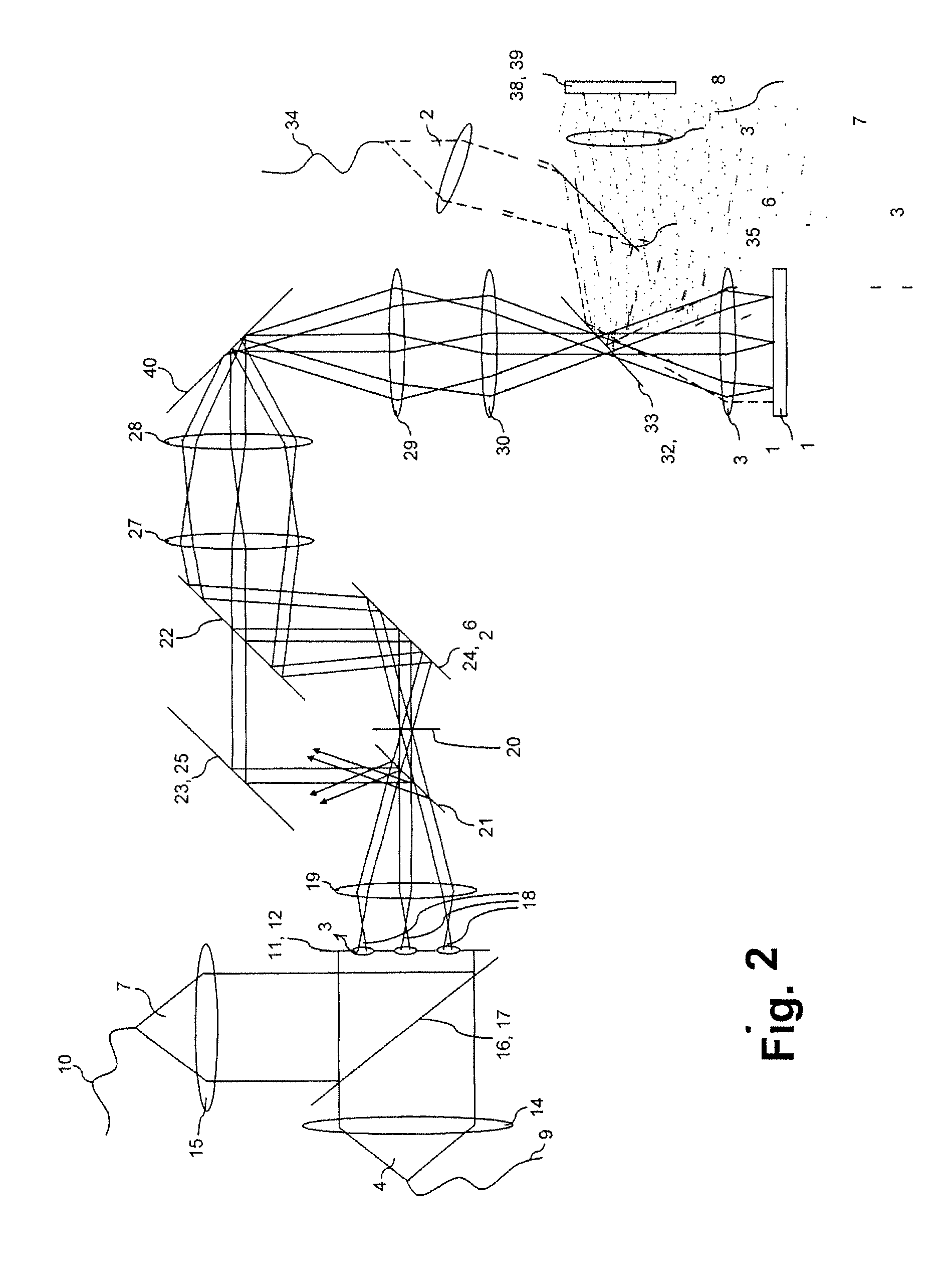
[0032]FIG. 1 shows a schematic of a cyclic illumination operation such as is used for high spatial resolution examination of samples beyond the diffraction limited resolving limit. In accordance with FIG. 1a, the first step is to use a switching signal 2 to bring into the first state Z1 in the entire sample space P to be recorded a substance that is provided in the sample 1 and can be converted repeatedly from a first state Z1 into a second state Z2, the first and the second states Z1, Z2 differing from one another in at least one optical property. In the exemplary embodiment illustrated in concrete terms, the first state Z1 is a fluorescing state A, and the second state Z2 is a non-fluorescing state B. In the example illustrated in concrete terms, the substance provided in the sample 1 is a photochromic substance whose molecules are brought into the fluorescence-capable state A by irradiation with light of a first wavelength, the switching signal 2. This happens ideally in that the...


PUM


Abstract

A method and a microscope, in particular a laser scanning fluorescence microscope, for high spatial resolution examination of samples, the sample (1) to be examined comprising a substance that can be repeatedly converted from a first state (Z1, A) into a second state (Z2, B), the first and the second states (Z1, A; Z2, B) differing from one another in at least one optical property, comprising the steps that the substance in a sample region (P) to be recorded is firstly brought into the first state (Z1, A), and that the second state (Z2, B) is induced by means of an optical signal (4), spatially delimited subregions being specifically excluded within the sample region (P) to be recorded, are defined with regard to increasing resolution in any desired direction and with regard to an increased imaging rate by the fact that the optical signal (4) is simultaneously concentrated at a number of focal points, and the focal points are focused into various sites of the sample (1).

Description

CROSS-REFERENCE TO RELATED PATENT APPLICATIONS[0001]The right of foreign priority is claimed under 35 U.S.C. § 119(a) based on Federal Republic of Germany Application No. 10 2006 009 832.3, filed Mar. 1, 2006, the entire contents of which, including the specification, drawings, claims and abstract, are incorporated herein by reference. The present application also claims benefit of priority to U.S. Provisional Application Ser. No. 60 / 853,448, filed Oct. 23, 2006, the entire contents of which are incorporated herein by reference.BACKGROUND OF THE INVENTION[0002]The invention relates to a method and a microscope, in particular a laser scanning fluorescence microscope, the sample to be examined comprising a substance that can be repeatedly converted from a first state into a second state, the first and the second states differing from one another in at least one optical property, comprising the steps that the substance in a sample region to be recorded is firstly brought into the first...

Claims


Application Information

Patent Timeline
IPC IPC(8): G02B21/06
CPCG02B27/58G02B21/0076
Inventor GUGEL, HILMARDYBA, MARCUS
Owner LEICA MICROSYSTEMS CMS GMBH
Why Eureka
Try Eureka