Circuit Protection Method, Protection Circuit and Power Supply Device Using The Protection Circuit

a protection circuit and circuit technology, applied in the direction of electric variable regulation, electrical equipment, instruments, etc., can solve the problems of affecting the reliability of the transistor and the desire for current limitation, and achieve the effect of simple structur

Inactive Publication Date: 2007-09-06
ROHM CO LTD
View PDF1 Cites 30 Cited by
  • Summary
  • Abstract
  • Description
  • Claims
  • Application Information

AI Technical Summary

Benefits of technology

[0011] The present invention is made in view of these problems, and the general purpose of the invention is to provide an ...

Problems solved by technology

However, even when designed to have a sufficient design margin like this, a large overcurrent exceeding the maximum allowable current will flow in the output transistor in case when an output load circuit is short-circuited or the like, causing a ...

Method used


Image

  • Circuit Protection Method, Protection Circuit and Power Supply Device Using The Protection Circuit
  • Circuit Protection Method, Protection Circuit and Power Supply Device Using The Protection Circuit
  • Circuit Protection Method, Protection Circuit and Power Supply Device Using The Protection Circuit

Examples


Embodiment Construction

[0038] The invention will now be described based on preferred embodiments which do not intend to limit the scope of the present invention but exemplify the invention. All of the features and the combinations thereof described in the embodiment are not necessarily essential to the invention.

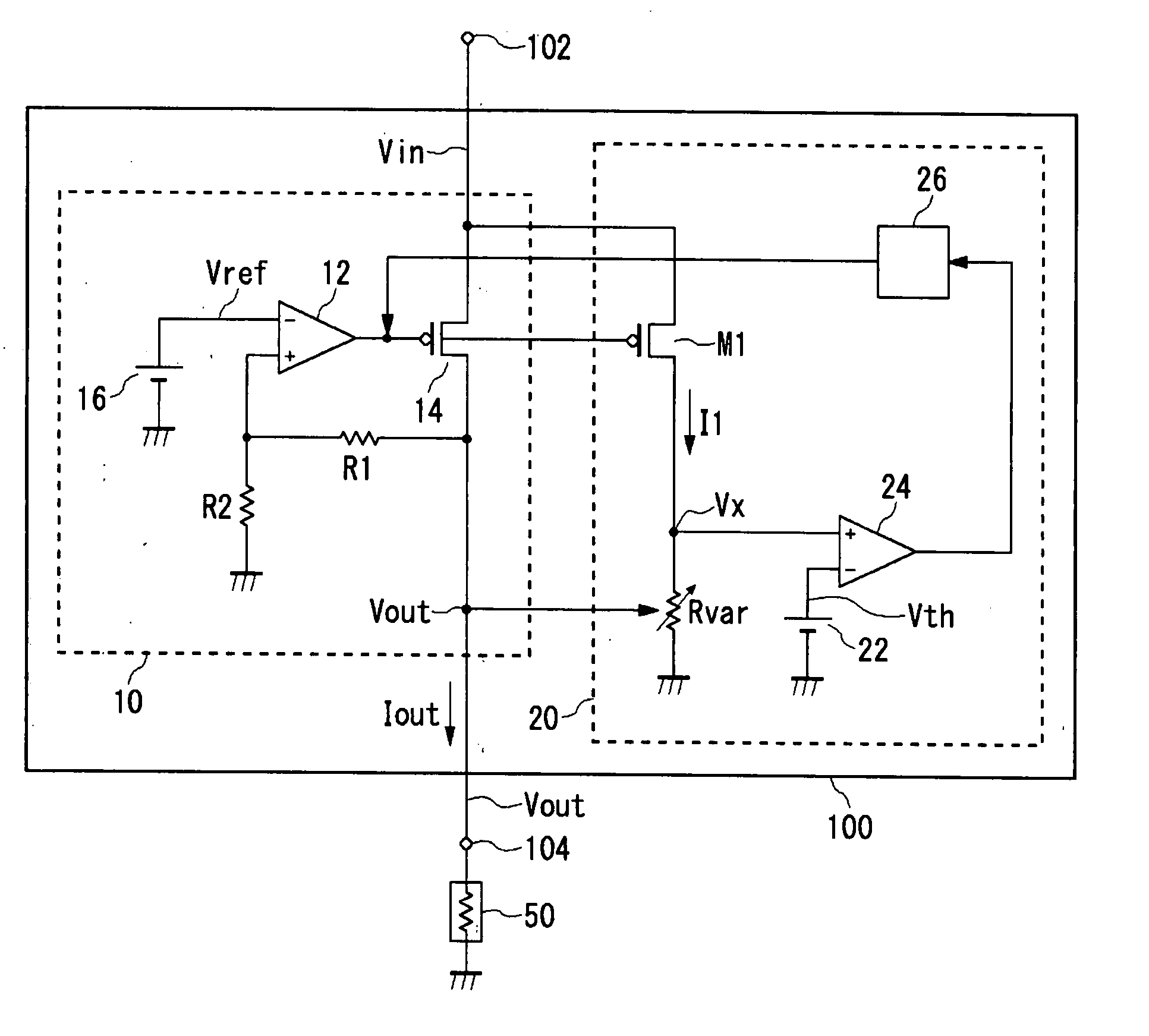
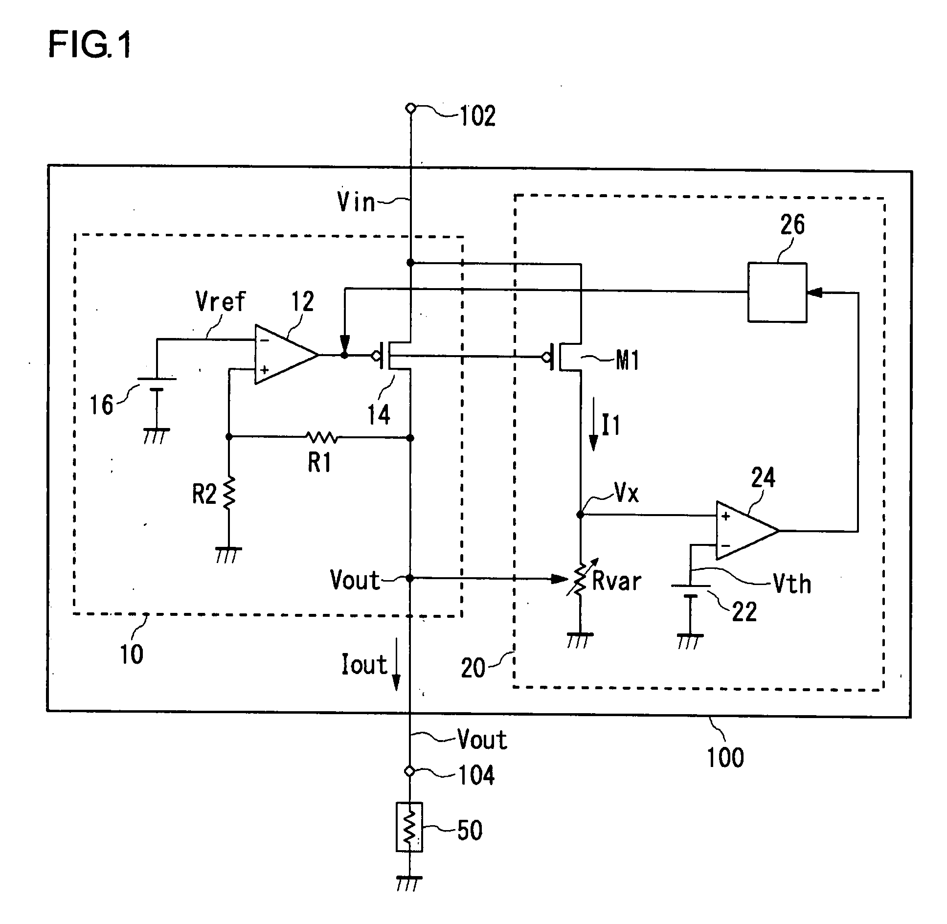
[0039]FIG. 1 is a circuit diagram showing a power supply apparatus 100 according to an embodiment of the present invention. In the accompanying drawings, the same constituting elements shall be denoted by the same reference symbols, and explanations will be omitted appropriately.

[0040] The power supply apparatus 100 includes a regulator 10 which adjusts the output voltage to a constant value based on the reference voltage, and an overcurrent protection circuit 20. The overcurrent protection circuit 20 detects the state of overcurrent in the regulator 10, and decreases the driving capability of the regulator when the circuit is overloaded or the load is short-circuited.

[0041] The power supply ap...


PUM


Abstract

An excess current protection circuit which can change a limited current corresponding to an output voltage by simple constitution. A power supply device (100) is provided with a regulator (10), which regulates the output voltage to be constant based on a reference voltage, and an excess current protection circuit (20). The regulator (10) is a general three-terminal regulator which includes an output transistor (14), an error amplifier (12) and resistors (R1, R2). The excess current protection circuit (20) detects an output current (lout) by a first transistor (M1), and converts it into a voltage by a variable resistor (Rvar). A voltage comparator (24) compares the voltage with a threshold voltage (Vth) corresponding to a limited current and detects an excess current status. A current adjusting circuit (26) drops driving performance of the regulator (10) when the excess current status is detected, and protects the circuit. The resistance value of the variable resistor (Rvar) is set based on an output voltage (Vout), and a value of the limited current is changed corresponding to the output voltage.

Description

BACKGROUND OF THE INVENTION [0001] 1. Field of the Invention [0002] The present invention relates to a protection circuit, and more particularly, relates to an overcurrent protection technology of a circuit. [0003] 2. Description of the Related Art [0004] In regulators or the like which stabilize voltages, Power MOSFETs (Metal Oxide Semiconductor Field Effect Transistors), IGBTs (Insulated Gate Bipolar Transistors) and Bipolar Power Transistors are, for example, provided as output transistor. These transistors are designed to have a sufficient margin with respect to an ordinal operating current, in the form of the maximum allowable current. [0005] However, even when designed to have a sufficient design margin like this, a large overcurrent exceeding the maximum allowable current will flow in the output transistor in case when an output load circuit is short-circuited or the like, causing a problem in that the reliability of the transistor is affected. In addition, even when a curren...

Claims


Application Information

Patent Timeline
IPC IPC(8): H02H9/02
CPCG05F1/575G05F3/24H02H9/02
Inventor ISHINO, TSUTOMU
Owner ROHM CO LTD
Why Eureka
Try Eureka