Control System For Internal Combustion Engine

a control system and internal combustion engine technology, applied in the direction of electric control, ignition automatic control, instruments, etc., can solve the problems of degraded drivability, reduce the accuracy of air-fuel ratio control, etc., and achieve the effect of improving the accuracy of ignition timing control

Inactive Publication Date: 2007-09-06
HONDA MOTOR CO LTD
View PDF17 Cites 10 Cited by
  • Summary
  • Abstract
  • Description
  • Claims
  • Application Information

AI Technical Summary

Benefits of technology

[0024] With the configuration of this preferred embodiment, the ignition timing is determined according to the corrected operating condition parameter when the load parameter is within a first predetermined range, whereas when the load parameter is within a second predetermined range different from the first predetermined range, the ignition timing is determined according to the detected flow rate of air. In this case, the corrected operating condition parameter and the detection value of the flow rate of air are both indicative of the amount of intake air. Therefore, by setting the firs

Problems solved by technology

As a result, when the operating condition parameter is corrected using the thus changed control state value, a value obtained by correcting the operating condition parameter is also changed in an osc

Method used


Image

  • Control System For Internal Combustion Engine
  • Control System For Internal Combustion Engine
  • Control System For Internal Combustion Engine

Examples


first embodiment

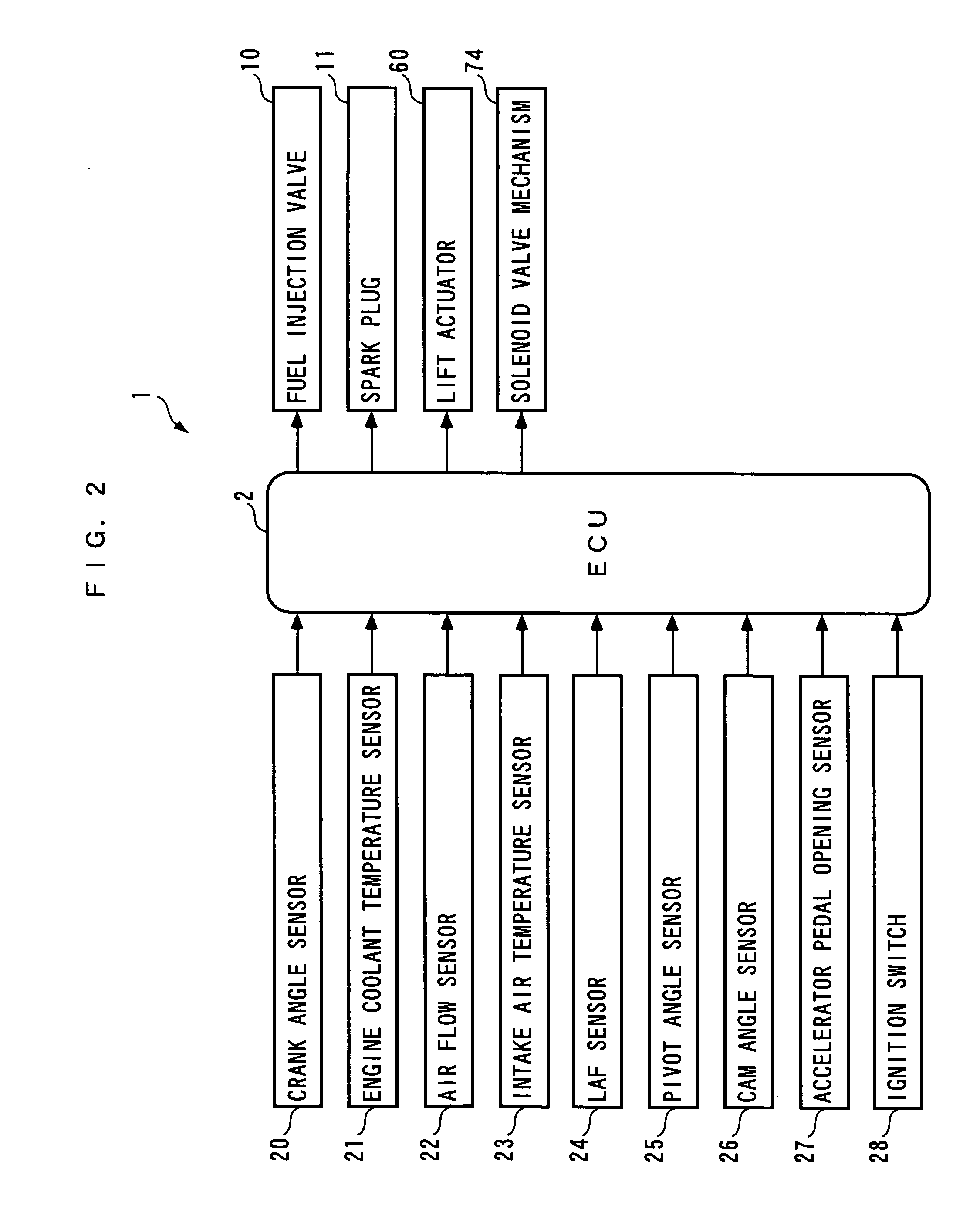
[0066] Hereafter, a control system for an internal combustion engine, according the present invention will be described with reference to the drawings. The control system 1 includes an ECU 2, as shown in FIG. 2. As described hereinafter, the ECU 2 carries out control processes, including an air-fuel ratio control process and an ignition timing control process, depending on operating conditions of the internal combustion engine (hereinafter simply referred to as “the engine”) 3.

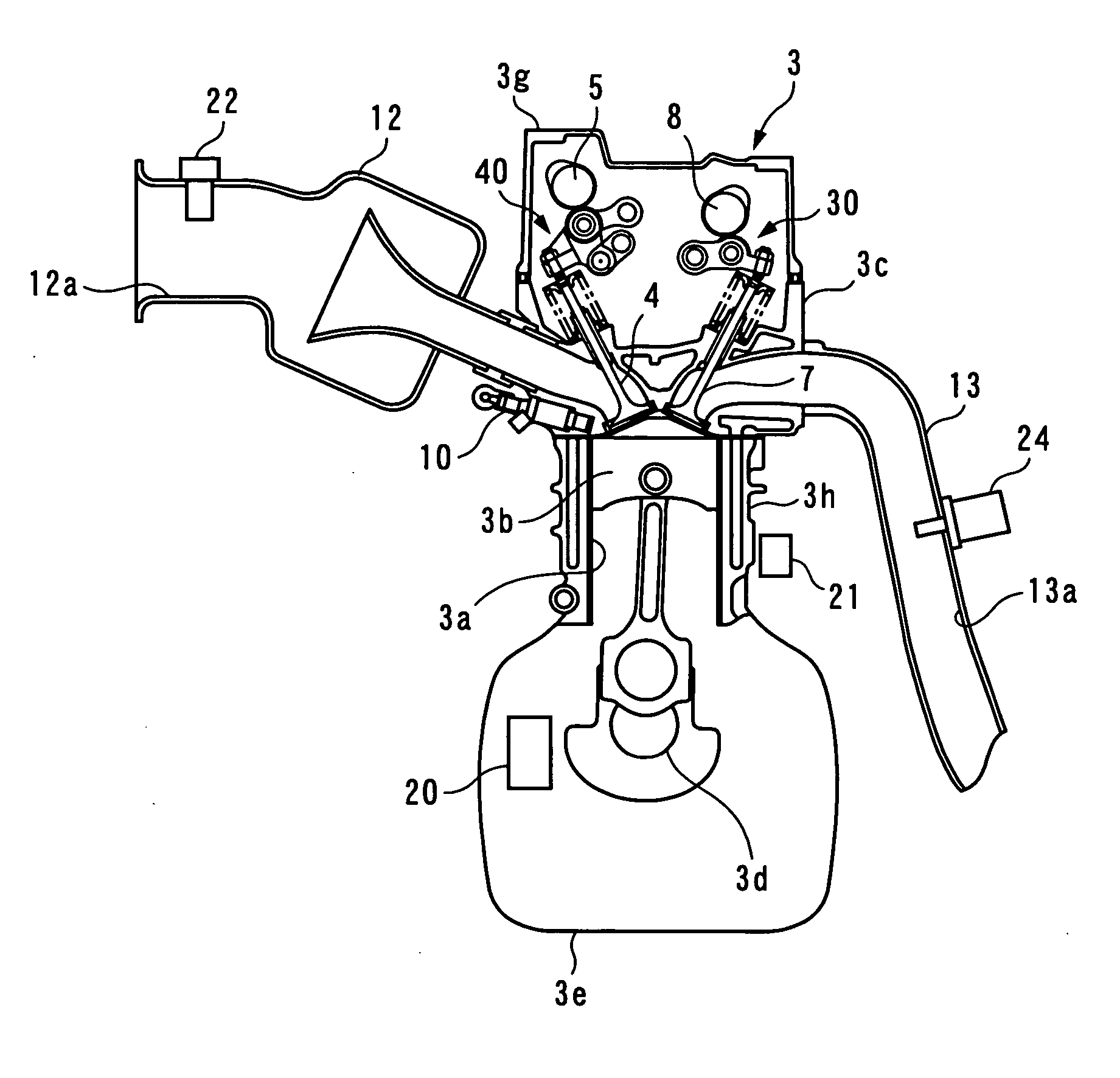
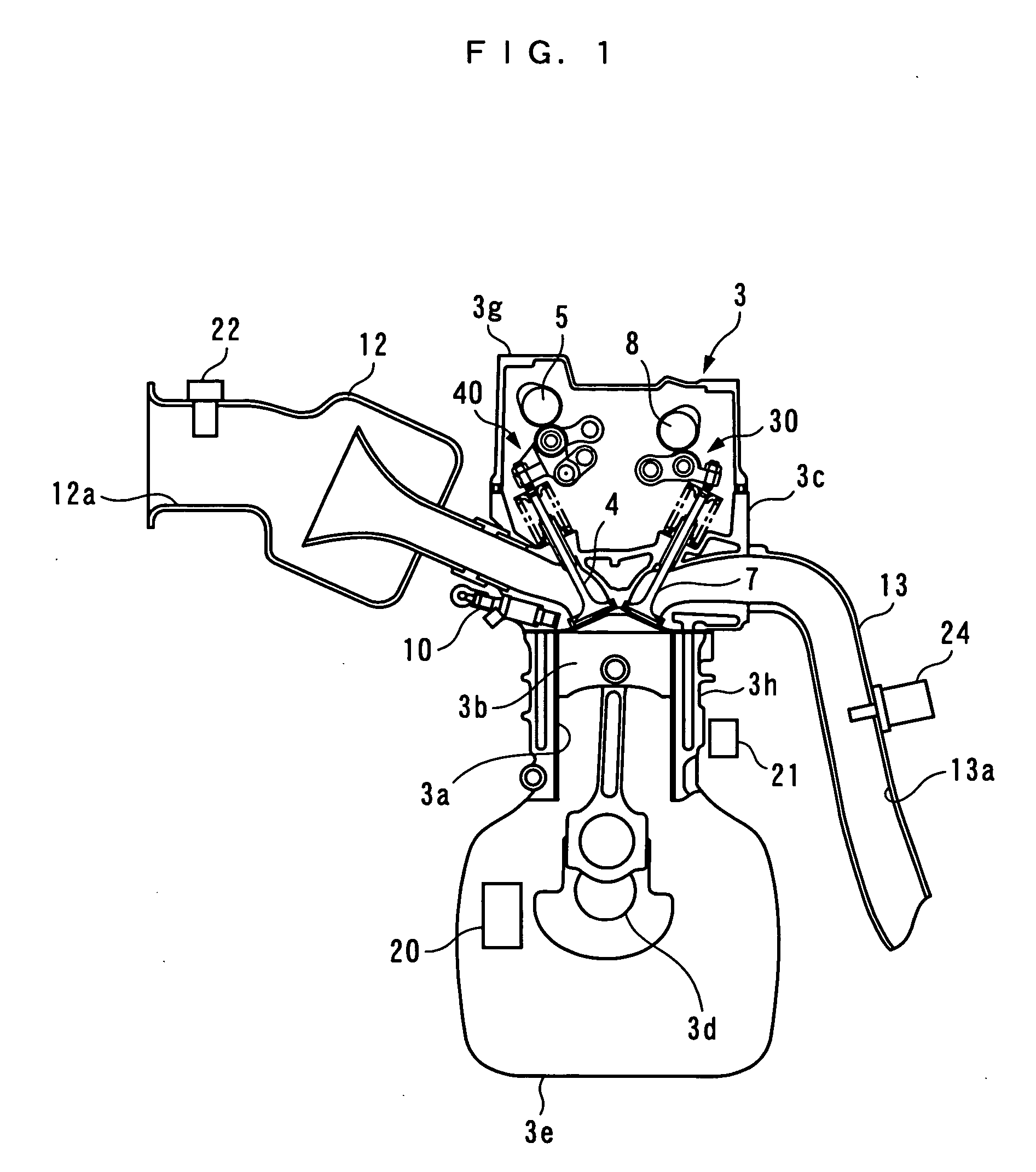
[0067] Referring to FIGS. 1 and 3, the engine 3 is an in-line four-cylinder gasoline engine having a four pairs of cylinders 3a and pistons 3b (only one pair of which is shown), and installed on a vehicle, not shown, provided with an automatic transmission. The engine 3 includes an intake valve 4 and an exhaust valve 7 provided for each cylinder 3a, for opening and closing an intake port and an exhaust port thereof, respectively, an intake camshaft 5 and intake cams 6 for actuating the intake valves 4, a varia...


PUM


Abstract

A control system for an internal combustion engine, which is capable of properly performing air-fuel ratio control and ignition timing control according to an actual amount of intake air, even when reliability of the results of detection of the operating condition of a variable intake mechanism is low. The control system 1 for controlling air-fuel ratio and ignition timing includes an ECU 2. The ECU 2 calculates a target air-fuel ratio KCMD (step 22), calculates an air-fuel ratio correction coefficient KSTR for performing feedback control of an air-fuel ratio (steps 2 to 7), calculates a statistically processed value KAF_LS of an air-fuel ratio index value (step 82), calculates a corrected valve lift Liftin_comp and a corrected cam phase Cain_comp according to the statistically processed value KAF_LS (steps 81 to 92), and determines a fuel injection amount TOUT according to the corrected valve lift Liftin_comp, the corrected cam phase Cain_comp, and the air-fuel ratio correction coefficient KSTR.

Description

FIELD OF THE INVENTION [0001] The present invention relates to a control system for an internal combustion engine, which controls the amount of intake air drawn into cylinders of the engine via a variable intake mechanism and controls an air-fuel ratio and ignition timing. BACKGROUND ART [0002] Conventionally, a control system for an internal combustion engine, which controls the amount of intake air drawn into cylinders of the engine via a variable intake mechanism, has been proposed in Patent Literature 1. This control system is comprised of an air flow sensor that detects the flow rate of air flowing through an intake passage of the engine, a crank angle sensor that detects a state of rotation of a crankshaft, an accelerator pedal opening sensor that detects an opening of an accelerator pedal (hereinafter referred to as “the accelerator pedal opening”), and a controller to which are input detection signals from these sensors. The controller calculates an engine speed based on the...

Claims


Application Information

Patent Timeline
IPC IPC(8): G06G7/70F01L1/34F01L13/00F02D13/02F02D37/02F02D41/14F02D41/22F02D43/00F02D45/00F02P5/04F02P5/15
CPCF01L1/34F01L1/3442F01L13/0021F01L13/0063F01L2001/3443F02D2041/001F02D41/1401F02D41/1454F02D41/187F02D41/221F02D37/02
Inventor YASUI, YUJISATO, MASAHIROSAITO, MITSUNOBUTAGAMI, HIROSHIHIGASHITANI, KOSUKE
Owner HONDA MOTOR CO LTD
Why Eureka
Try Eureka