Method and apparatus for electropolishing metallic stents

Active Publication Date: 2007-09-13
VIANT AS&O HLDG LLC +1
View PDF10 Cites 47 Cited by
  • Summary
  • Abstract
  • Description
  • Claims
  • Application Information

AI Technical Summary

Problems solved by technology

A rough outer surface may not only cause increased frictional obstruction, but may also damage the lining of the vessel wall during insertion.
Furthermore, smooth surfaces decrease the probability of thrombogenesis and corrosion.
Since the processing to form metallic stents often results in a product initially having undesirable burrs, sharp ends or d

Method used


Image

  • Method and apparatus for electropolishing metallic stents
  • Method and apparatus for electropolishing metallic stents
  • Method and apparatus for electropolishing metallic stents

Examples


example

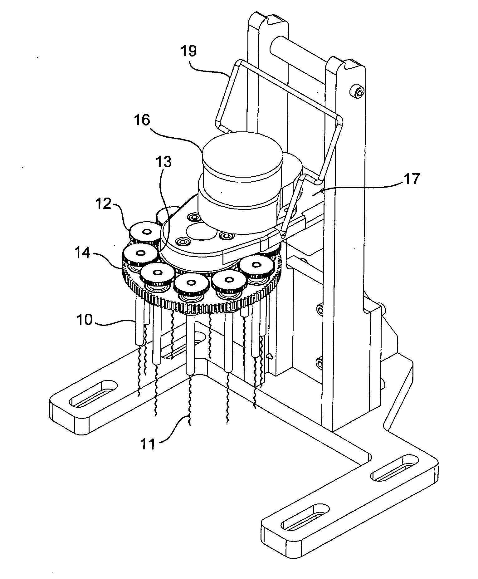
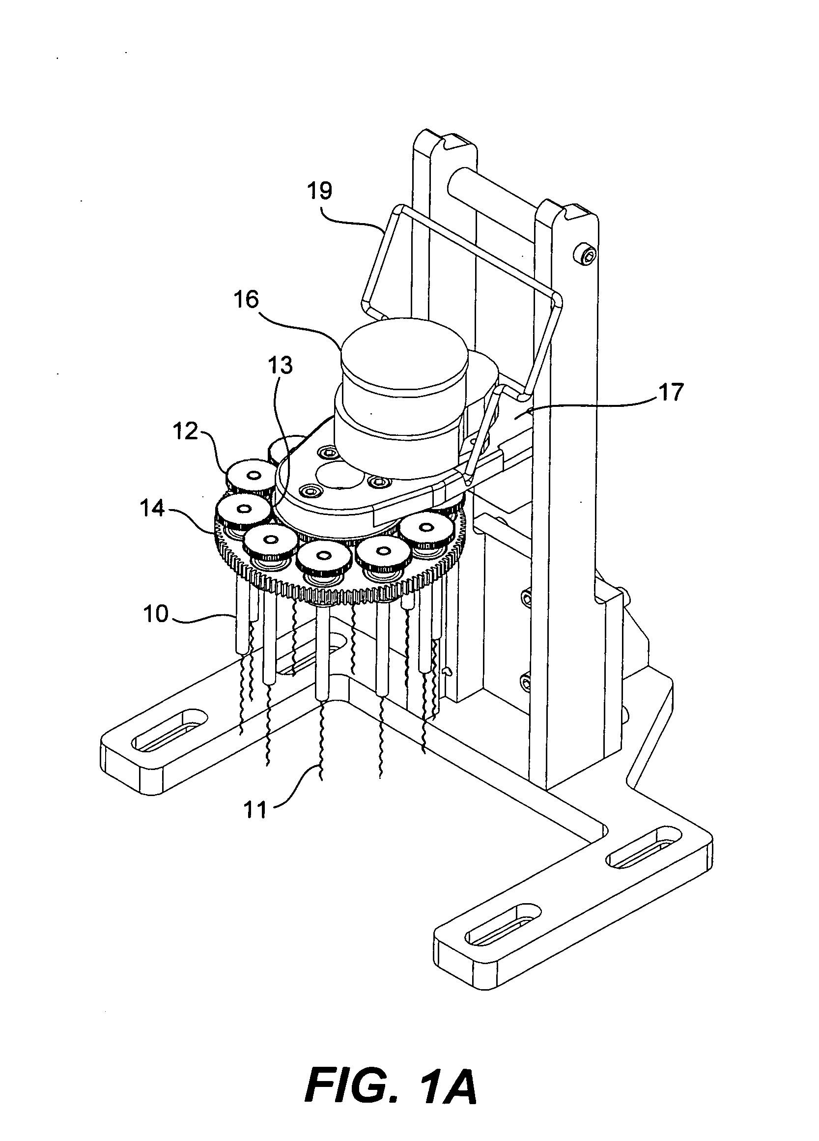
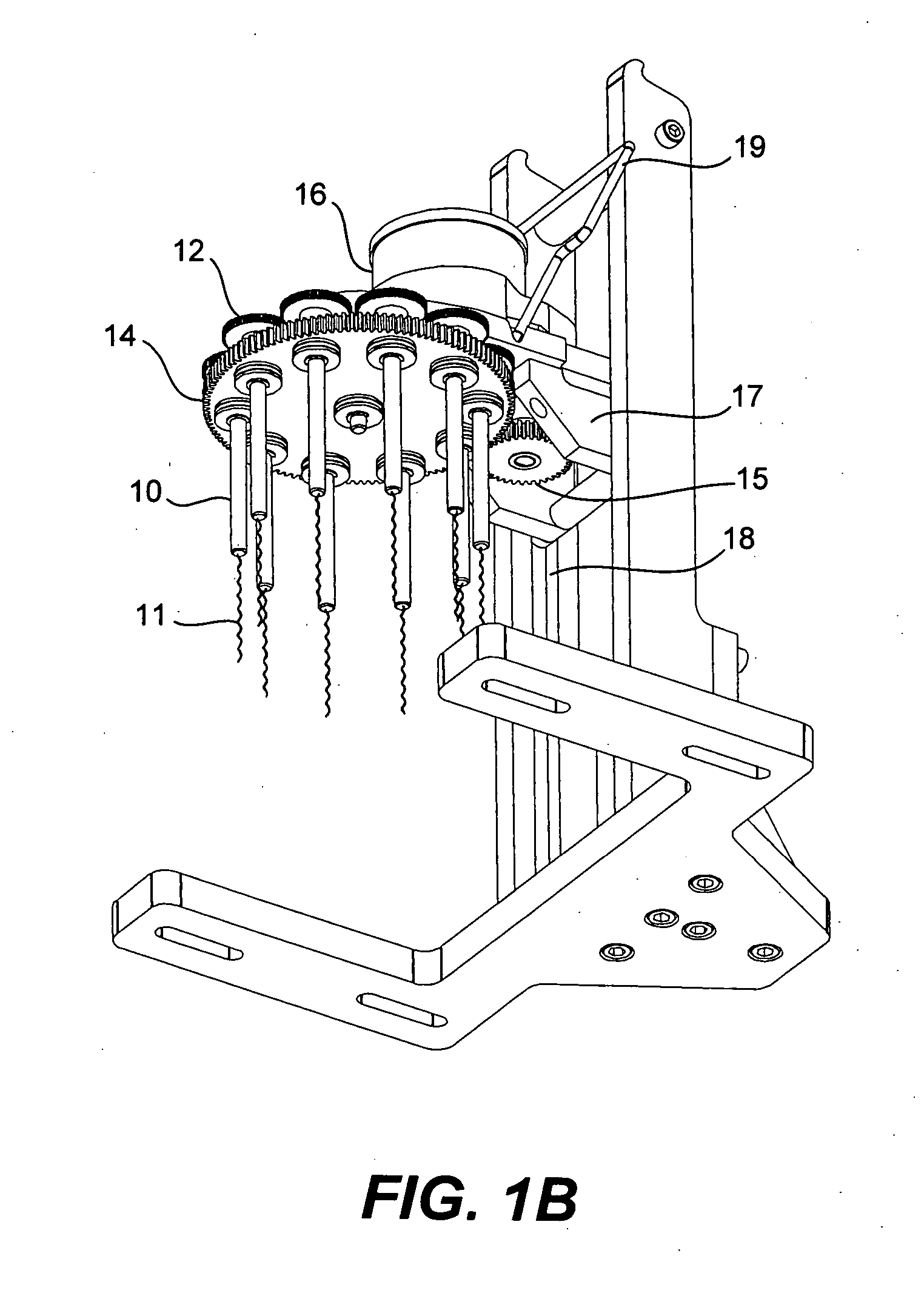
[0065] Five dry identical stents are inserted onto five of the adapter on the receiver by sliding over the corkscrew or undulating contact points. While agitating the electropolishing solution (4 volume percent ethylene glycol, 10 volume percent sulfuric acid, 86 volume percent methanol) the stents are lowered on the apparatus into the electropolishing solution. The positive lead from the electrical source is attached to the apparatus and the motor is turned on to revolve and rotate the stents in the solution. When the cycle time has elapsed (depending on the size and type of stent) the stents are removed from the receiver and submerged in a container of methanol. Each stent is rotated while submerged. The stents are then re-immersed in the electropolishing solution for another polishing cycle. The polishing cycle is repeated between two to four polishing cycles. The stents removed from the adapters and placed into a purified water rinse for about 30 seconds. The stents are then rem...


PUM

PropertyMeasurementUnit
Angleaaaaaaaaaa
Temperatureaaaaaaaaaa
Shapeaaaaaaaaaa

Abstract

An apparatus and method are provided for simultaneously electropolishing a plurality of metallic stents. A plurality of elongated members on the apparatus are movably engaged with a plate such that movement of the plate relative to the elongated members causes each of the elongated members to rotate on its respective longitudinal axis when immersed in an electrolytic solution. A continuous cathode is located in close proximity to each of the elongated members when they are immersed in the electrolytic solution.

Description

RELATED APPLICATION [0001] This application is related to the application entitled “Method of Descaling Metallic Devices” by inventor Sanjay Shrivastava, filed on the same date herewith. BACKGROUND OF THE INVENTION [0002] The present invention relates generally to providing an apparatus and method for electropolishing products made from metals, and in particular, electropolishing metallic medical devices such as stents, made of stainless steel, titanium, tungsten, nickel-titanium, tantalum, cobalt-chromium-tungsten, etc. While the apparatus and method are described herein as being applicable mainly to medical stents, in particular intravascular stents, the invention is not limited to such medical products. For example, the methods may be applied to electropolish metallic automotive or aerospace components. [0003] Stents are generally tube-shaped intravascular devices placed within a blood vessel to maintain the patency of the vessel and, in some cases, to reduce the development of r...

Claims


Application Information

Patent Timeline
IPC IPC(8): B23H5/06C25F7/00C25C7/02
CPCC25F7/00C25F3/16
Inventor SHRIVASTAVA, SANJAYMOLONEY, FRANKYRIBARREN, TRAVISFARINA, JEFFREYTHOMAS, JOHNYOUNG, JAMES
Owner VIANT AS&O HLDG LLC
Why Eureka
Try Eureka