
Method for manufacturing plugged honeycomb structure and plug filling jig

a technology of honeycomb and plug filling, which is applied in the direction of manufacturing tools, ceramic shaping apparatus, etc., can solve problems such as environmental pollution

Inactive Publication Date: 2007-09-13
NGK INSULATORS LTD
View PDF2 Cites 22 Cited by
  • Summary
  • Abstract
  • Description
  • Claims
  • Application Information

AI Technical Summary

Benefits of technology

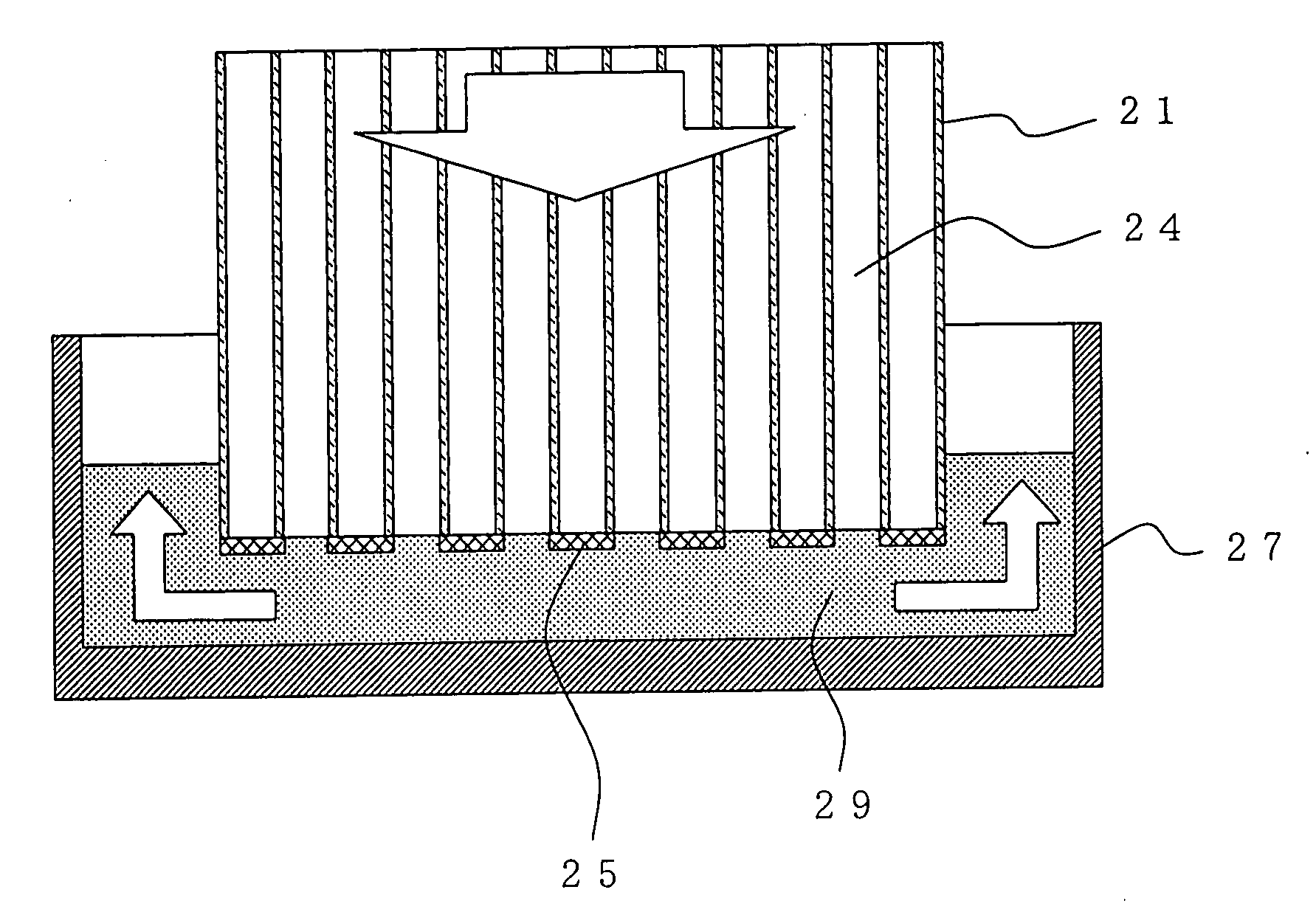
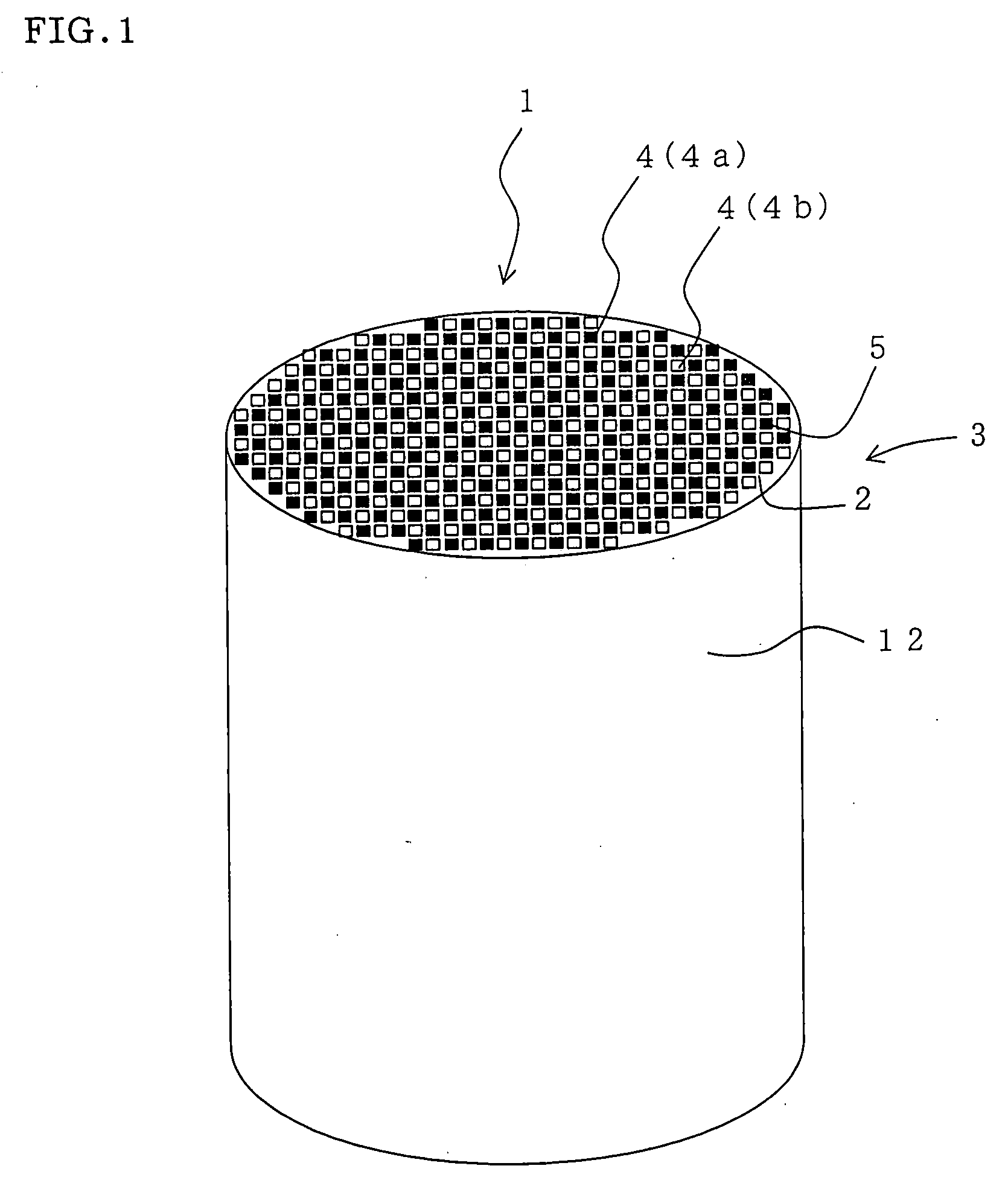
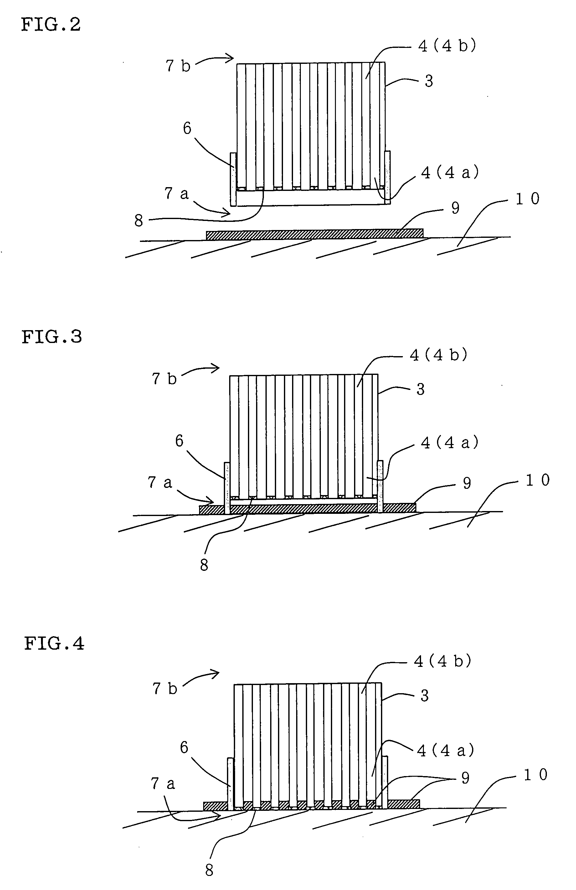
[0011][1] A method for manufacturing a plugged honeycomb structure comprising a cylindrical honeycomb structure including partition walls formed of a porous body and a large number of cells acting as fluid passageways divided and formed by said partition walls, and plugged portions plugging openings of some of said cells of said honeycomb structure, the method comprising the step of pressing one end of said honeycomb structure at the side where a plug filling jig is disposed onto a ceramic slurry to thus introduce said ceramic slurry into cells to be plugged (plugged cells) to form said plugged portions, wherein said plug filling jig is disposed by one of the steps selected from the step (A) and step (B) specified below: step (A) disposing said plug filling jig so that it covers the side of a periphery of said one end of said honeycomb structure at the side where plugged cells are open and a tip of said plug filling jig locates being protruded from an end surface of the side of said one end, to separate the end surface of the side of said one end from a surrounding space; and step (B) disposing said plug filling jig so that it covers the side of a periphery of said one end of said honeycomb structure on the side where plugged cells are open and a tip of said plug filling jig locates at the same position as an end surface of said one end, to increase an outer diameter of a portion of said honeycomb structure increase at the side of said one end.
[0015][5] The method for manufacturing a plugged honeycomb structure according to any one of [1] to [4], wherein a material having rigidity so that a deformation in the radial direction of said honeycomb structure does not occur when it is pressed onto said ceramic slurry is used as said plug filling jig.
[0023][13] A plug filling jig disposed at one end of a honeycomb structure at the side where plugged cells are open, and used to increase an outer diameter of a portion of said honeycomb structure at the side of said one end and press said one end of said honeycomb structure onto a ceramic slurry to thus introduce said ceramic slurry into said plugged cells, said plug filling jig comprising: a cylindrical body having an inner diameter corresponding to a size of a periphery of said honeycomb structure having said cells to be plugged formed therein and a thickness capable of increasing an outer diameter of a portion of said honeycomb structure at the side of said one end, wherein said plug filling jig can be mounted and fixed on the side of said one end of said honeycomb structure.

Problems solved by technology

Particulates emitted into the atmosphere causes environmental pollution.

Method used


Image

  • Method for manufacturing plugged honeycomb structure and plug filling jig
  • Method for manufacturing plugged honeycomb structure and plug filling jig
  • Method for manufacturing plugged honeycomb structure and plug filling jig

Examples


example 1

[0105]In this example, a cylindrical honeycomb structure including partition walls formed of a porous body where a large number of cells acting as fluid passageways were divided and formed by the partition walls was provided as a honeycomb structure to be used. The honeycomb structure was comprised cordierite and had a shape of a cylinder whose end surface was a circle 250 mm across, a rectangular cell shape, a partition wall thickness of 0.3 mm (12 mil), and a cell density of 46.5 cells / cm2 (300 cells / square inch). On the diagonal line on the end surface of the honeycomb structure were 85 cells. 1 mil is equal to one thousandth of an inch and is approximately 0.025 mm.

[0106]The honeycomb structure was manufactured by adjusting a clay to an appropriate viscosity, performing extrusion molding on the clay by using a die having the above cell shape, partition wall thickness and cell density, drying the resulting green body, and cutting both end surfaces to provide smooth surfaces.

[0107...

example 2

[0111]In this example, a cylindrical honeycomb structure including partition walls formed of a porous body and a large number of cells acting as fluid passageways divided and formed by the partition walls was provided as a honeycomb structure to be used. The honeycomb structure was comprised cordierite and had a shape of a cylinder whose end surface was a circle 210 mm across, a rectangular cell shape, a partition wall thickness of 0.3 mm (12 mil), and a cell density of 46.5 cells / cm2 (300 cells / square inch). On the diagonal line on the end surface of the honeycomb structure were 70 cells.

[0112]The honeycomb structure was manufactured by adjusting a clay to an appropriate viscosity, performing extrusion molding on the clay by using a die having the above cell shape, partition wall thickness and cell density, drying the resulting green body, and cutting both end surfaces to provide smooth surfaces.

[0113]On such a honeycomb structure, a plug filling jig formed of a cylindrical body of...

example 3

[0115]On a honeycomb structure similar to that in Example 2, a plug filling jig formed of a cylindrical body of a natural rubber having a thickness of 8 mm was disposed. By using the same method as that in Example 2, a ceramic slurry was introduced into plugged cells. After the ceramic slurry was introduced into plugged cells, each plugging depth was measured for 70 cells on the diagonal line of the end surface. FIG. 16 is a graph showing each plugging depth in the 70 cells on the diagonal line of the end surface. In FIG. 16, vertical axis shows a plugging depth (mm) while horizontal axis shows the positions of the 70 cells on the diagonal line of the end surface. Table 2 shows the plugging depth (mm) in the 10 cells at the side of the periphery (cell positions 1 to 10 and 61 to 70 in FIG. 16).


PUM

PropertyMeasurementUnit
thickaaaaaaaaaa
thickaaaaaaaaaa
viscosityaaaaaaaaaa

Abstract

There is disclosed a method for manufacturing a plugged honeycomb structure capable of manufacturing a plugged honeycomb structure in which the plugging depth is uniform. A method for manufacturing a plugged honeycomb structure, according to the invention, includes disposing a plug filling jig 6 so that it covers the side of the periphery of one end 7a of the honeycomb structure 3 at the side where plugged cells 4a are open and its tip locates being protruded from the end surface of the one end 7a, the end surface of the side of the one end 7a is separated from the surrounding space and the one end 7a of the honeycomb structure 3 where the plug filling jig 6 is disposed is pressed onto a ceramic slurry to thus introduce the ceramic slurry into the plugged cells 4a to form plugged portions.

Description

BACKGROUND OF THE INVENTION[0001]1. Field of the Invention[0002]The present invention relates to a method for manufacturing a plugged honeycomb structure and a plug filling jig. In particular, the invention relates to a method for manufacturing a plugged honeycomb structure capable of manufacturing a plugged honeycomb structure in which the plugging depth is uniform, and a plug filling jig preferably used in such a method for manufacturing a plugged honeycomb structure.[0003]2. Description of the Related Art[0004]Exhaust gas emitted from internal-combustion engines such as a diesel engine or various types of combustion equipment contains a large volume of particulates (particulate matter) in which main ingredient is soot (black smoke). Particulates emitted into the atmosphere causes environmental pollution. Thus, it is a general practice that the exhaust gas channel from an internal-combustion engine mounts a filter to trap particulates.[0005]An example of a filter used for this pur...

Claims


Application Information

Patent Timeline
Patent Type & Authority Applications(United States)
IPC IPC(8): B29C45/14
CPCB28B11/007B28B11/006
Inventor HATANO, TATSUHIKOENOMOTO, AKIO
Owner NGK INSULATORS LTD
Learn More