Microstrip Antenna and Clothed Attached with the Same

a microstrip antenna and clothed technology, applied in the direction of resonant antennas, flexible aerials, collapsible antennas, etc., can solve the problems of hard and heavy whole assembly, and insufficient soldering on to the surface nickel layer

Inactive Publication Date: 2007-09-13
NAT INST OF INFORMATION & COMM TECH
View PDF6 Cites 11 Cited by
  • Summary
  • Abstract
  • Description
  • Claims
  • Application Information

AI Technical Summary

Benefits of technology

[0009] Namely, the microstrip antenna of the present invention is equipped with a nearly flat plate-like radiating conductor, a nearly flat plate-like ground conductor having larger area than the radiating conductor, and a dielectric substrate set between the radiating conductor and the ground conductor, wherein one terminal of a feeding cable is connected to the radiating conductor, and the other terminal is connected to the ground conduct

Problems solved by technology

In addition, a radiating conductor or a ground conductor was also stiff, and the whole assembly was a hard and heavy one.
In the case when a cloth woven by a polyester fiber which coated with copper and covered with a surface nickel layer on

Method used


Image

  • Microstrip Antenna and Clothed Attached with the Same
  • Microstrip Antenna and Clothed Attached with the Same

Examples


example

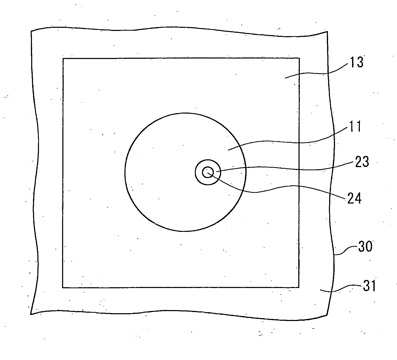
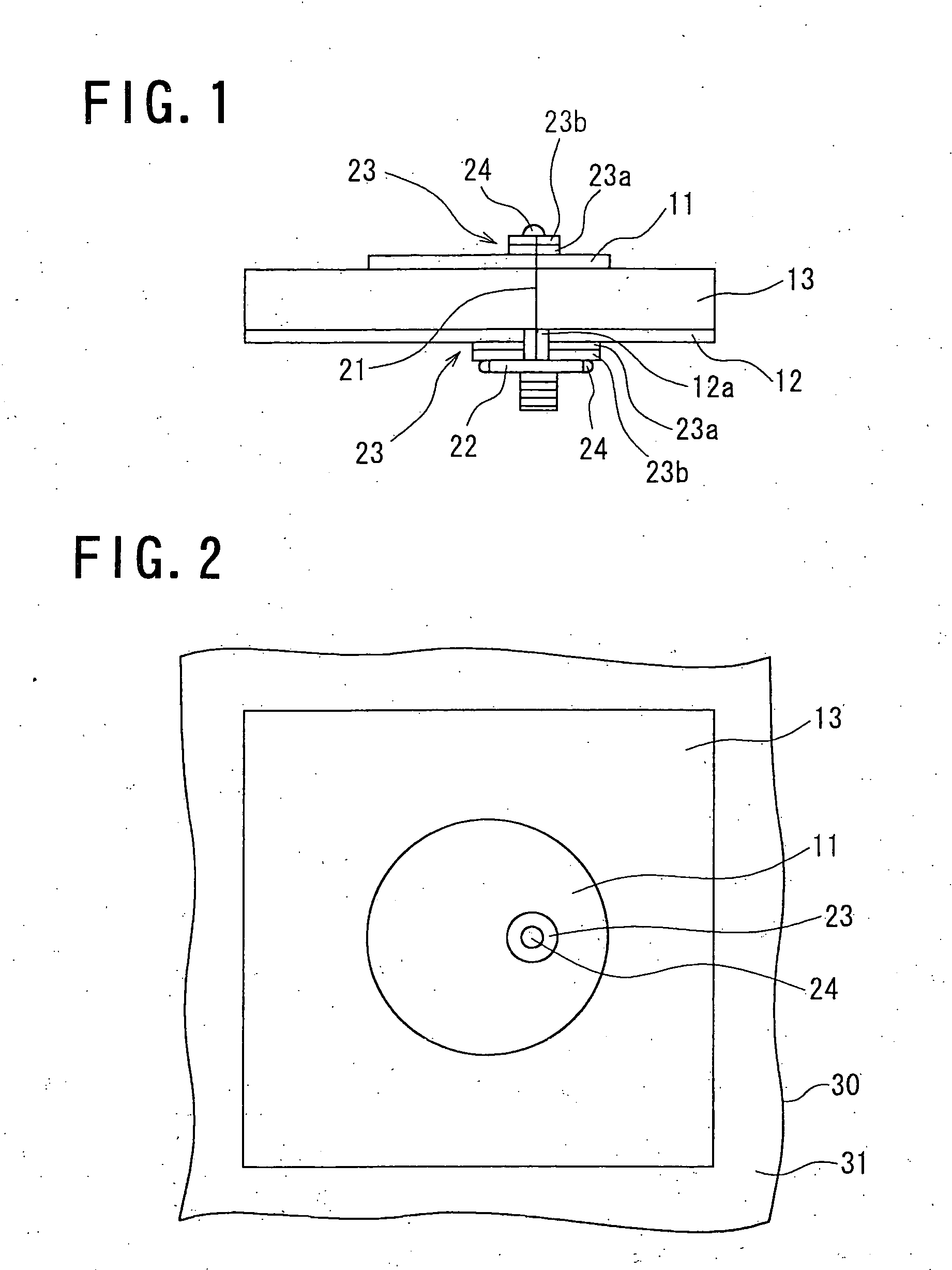
[0043] An antenna having structure shown in FIG. 1 was produced for experiment to confirm operability of a microstrip antenna of the present invention.

[0044] As the radiating conductor (11), conductive cloth having circular shape with a diameter of 60 mm, a thickness of 0.15 mm, a surface density of 80 g / m2, and a reflection loss and a transmission loss at 2.5 GHz of 0.03 dB and 74 dB, respectively, was used.

[0045] As the ground conductor (12), conductive cloth having square shape with a side length of 150 mm, a thickness of 0.15 mm, a surface density of 80 g / m2, and a reflection loss and a transmission loss at 2.5 GHz of 0.03 dB and 74 dB, respectively, was used.

[0046] As the dielectric substrate (13), cheap square felt having a side length of 150 mm, a thickness of 1 mm, and a relative dielectric constant of 1.43 was used.

[0047] As a feeding connector, a nearly square shape SMA connector having a side length of grounding surface contacting with the ground conductor (12) of 12....


PUM


Abstract

In a microstrip antenna equipped with a nearly flat plate-like radiating conductor, a nearly flat plate-like ground conductor having larger area than the radiating conductor, and a dielectric substrate set between the radiating conductor and the ground conductor, and one terminal of a feeding cable is connected to the radiating conductor, and the other terminal is connected to the ground conductor, the radiating conductor and the ground conductor are composed of nearly cloth-like substances having flexibility and conductivity, and also the dielectric substrate is composed of a nearly cloth-like substance having flexibility and insulation property, and the connection of the terminal of the feeding cable to the radiating conductor or the ground conductor is composed of by soldering through a conductive medium.

Description

TECHNICAL FIELD [0001] The present invention relates to a microstrip antenna having flexibility to be attachable on clothes, and clothes attached with the antenna. BACKGROUND ART [0002] A microstrip antenna is used as an antenna for a mobile station such as an automobile, or an antenna for a cellular phone and an antenna for satellite communication. [0003] A dielectric substrate or a feeding circuit substrate of a conventional microstrip antenna was hard and heavy one. In addition, a radiating conductor or a ground conductor was also stiff, and the whole assembly was a hard and heavy one. [0004] On the contrary, the present applicants have disclosed, in Japanese application No. 2002-60010, a technology for attaching a microstrip antenna to clothes or a hat and the like, by composing a dielectric substrate, a radiating conductor or a ground conductor by flexible material. [0005] When a conventional microstrip antenna was fed by a pin using a coaxial connector, an inner conductor of t...

Claims


Application Information

Patent Timeline
IPC IPC(8): H01Q13/08H01Q1/08H01Q1/27H01Q9/04
CPCH01Q1/085H01Q9/0407H01Q1/273H01R4/02H01R4/04H01R11/01
Inventor TANAKA, MASATOJANG, JAE-HYEUK
Owner NAT INST OF INFORMATION & COMM TECH
Why Eureka
Try Eureka