Manufacturing method of substrate for ink jet head and manufacturing method of ink jet recording head

a manufacturing method and ink jet recording technology, applied in the manufacturing of instruments, recording devices, manufacturing tools, etc., can solve the problems of difficult to achieve stable manufacture, poor production efficiency, and limited distance between the bottom surface of the substrate and the bent portion of the “>” shape, and achieve stable manufacturing of the substrate. , the effect of high production efficiency and high precision

Inactive Publication Date: 2007-09-13
CANON KK
View PDF13 Cites 35 Cited by
  • Summary
  • Abstract
  • Description
  • Claims
  • Application Information

AI Technical Summary

Benefits of technology

[0011]In view of the above-mentioned circumstance, the present invention aims to provide a manufacturing method of a substrate for an ink jet head capable of stably manufacturing an ink jet head substrate with high production efficiency. Specifically, the present invention aims to manufacture a substrate for an ink jet head, which has a supply opening whose opening width is reduced than a conventional one, with high precision and in a short time.

Problems solved by technology

However, the method disclosed in U.S. Pat. No. 6,107,209 has a limitation on the distance from the bottom surface of the substrate to the bent portion of the “” shape.
Further, the final shape varies depending upon the oxygen concentration in the silicon substrate, whereby it is difficult to achieve a stable manufacture.
However, since it takes much time to etch by the dry etching, the problem of poor production efficiency arises.

Method used


Image

  • Manufacturing method of substrate for ink jet head and manufacturing method of ink jet recording head
  • Manufacturing method of substrate for ink jet head and manufacturing method of ink jet recording head
  • Manufacturing method of substrate for ink jet head and manufacturing method of ink jet recording head

Examples


Embodiment Construction

[0020]Subsequently, an embodiment of the present invention will be explained with reference to drawings.

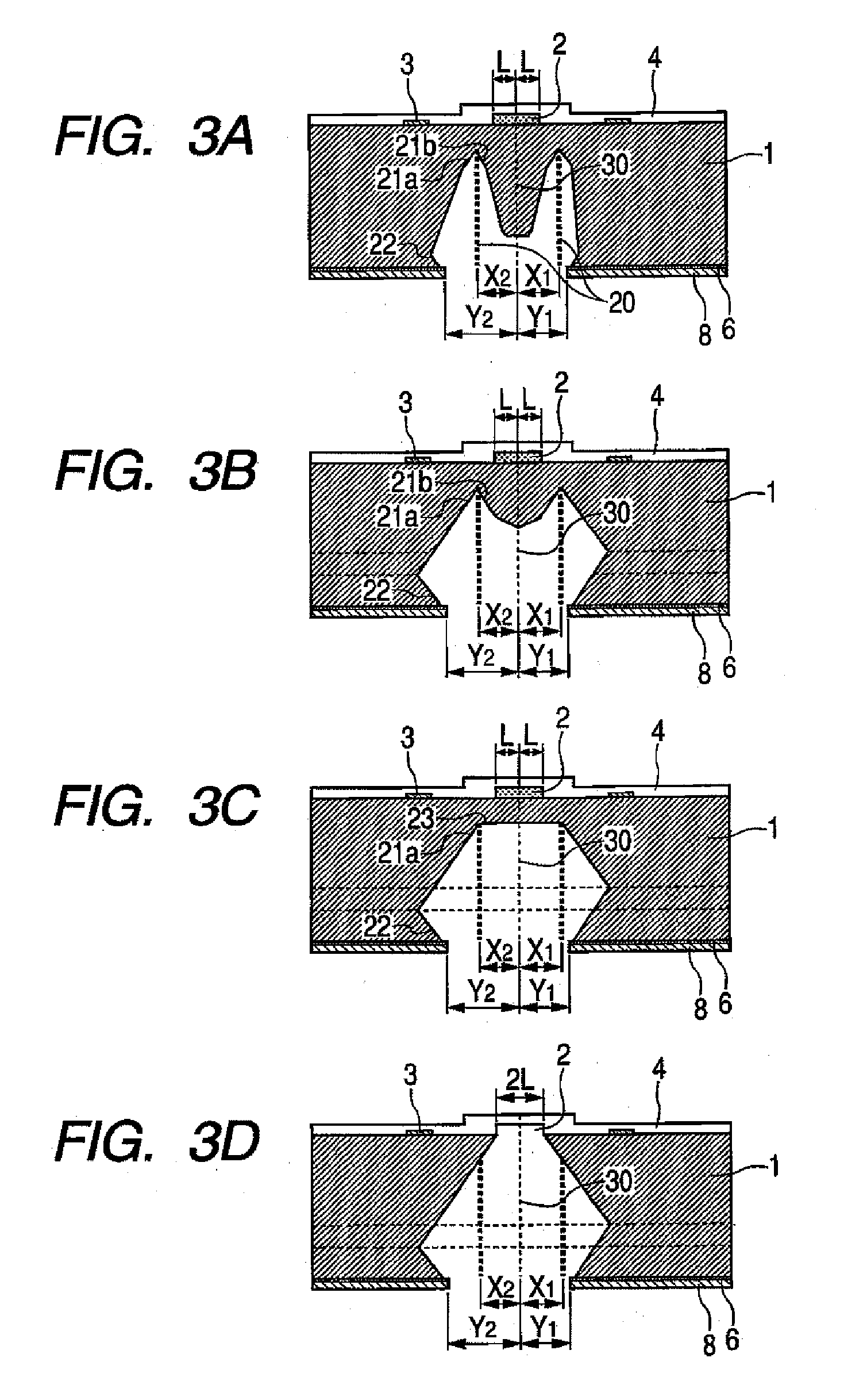
[0021]The feature of the manufacturing method of a substrate for an ink jet head according to the present invention is such that an anisotropic etching is performed after a non-through hole (hereinafter referred to as “guide hole”) is formed by, for example, a laser processing, in a method for forming an ink supply opening by using an anisotropic etching. This will be explained in detail.

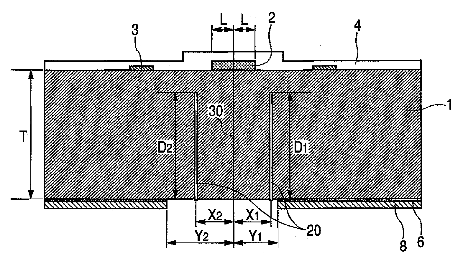
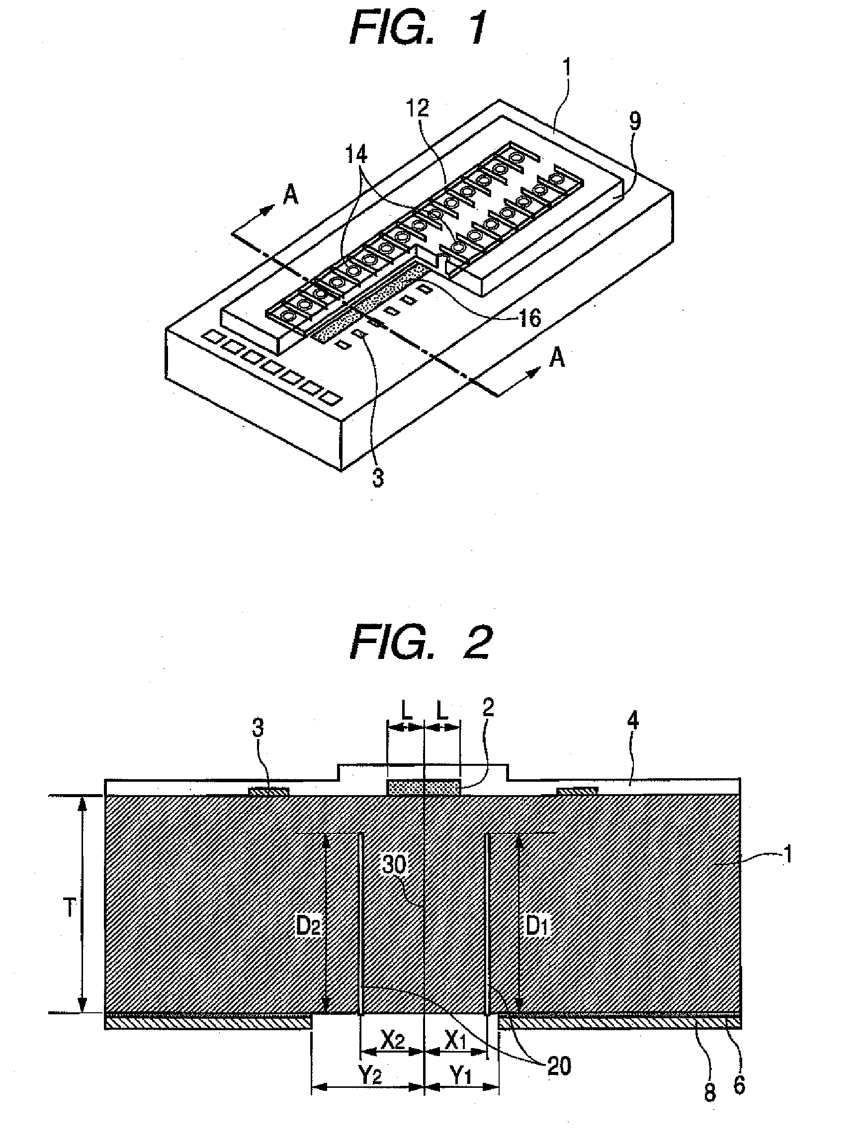
[0022]FIG. 1 shows a part of an ink jet recording head according to one embodiment of the present invention.

[0023]This ink jet recording head (liquid discharge head) has a silicon substrate 1 having energy generating elements (liquid discharge energy generating elements) 3, which generate energy used for discharging ink, arranged thereon in two rows at a predetermined pitch. A polyether amide layer (not shown) that is an adhesive layer is formed on the silicon substrate 1. Further, formed on the s...


PUM

PropertyMeasurementUnit
areaaaaaaaaaaa
thicknessaaaaaaaaaa
distanceaaaaaaaaaa

Abstract

The present invention provides a manufacturing method of a substrate for an ink jet head including forming an ink supply opening to a silicon substrate, including (a) forming, at the back surface of the silicon substrate, an etching mask layer, which has an opening that is asymmetric with a center line, extending in the longitudinal direction, of an area on the surface of the silicon substrate where the ink supply opening is to be formed; (b) forming a non-through hole on the silicon substrate via the opening on the etching mask layer; and (c) forming the ink supply opening by performing a crystal anisotropic etching to the silicon substrate from the opening.

Description

BACKGROUND OF THE INVENTION[0001]1. Field of the Invention[0002]The present invention relates to a manufacturing method of a substrate for an ink jet head that discharges ink for performing recording onto a recording medium in accordance with an ink jet system, and a manufacturing method of an ink jet head.[0003]2. Related Background Art[0004]There has conventionally been known an ink jet head (hereinafter referred to as “side shooter type head”) that discharges ink to the portion above an ink discharge pressure generating element. In this type of ink jet head, a through hole (ink supply opening) is formed on a substrate having a discharge energy generating section formed thereto, wherein ink is supplied from the back surface opposite to the surface on which the discharge energy generating section is provided.[0005]U.S. Pat. No. 6,143,190 discloses a manufacturing method of this type of ink jet head. It discloses the manufacturing method including the steps described below in order ...

Claims


Application Information

Patent Timeline
Patent Type & Authority Applications(United States)
IPC IPC(8): H01L21/302H01L21/461
CPCB41J2/14145B41J2/1603B41J2/1628B41J2/1629Y10T29/49401B41J2/1632B41J2/1634B41J2/1639B41J2/1645B41J2/1631
Inventor YAMAMURO, JUNKOYAMA, SHUJIONO, KENJISAKAI, TOSHIYASU
Owner CANON KK
Why Eureka
Try Eureka