Fine Particle

a technology of fine particles and catalysts, applied in the field of fine particles, can solve the problems of difficult control of the above factors and the reduction of the activity of the catalyst, and achieve the effect of easy evaporated

Inactive Publication Date: 2007-09-13
TAKAYUKI ABE +1
View PDF0 Cites 16 Cited by
  • Summary
  • Abstract
  • Description
  • Claims
  • Application Information

AI Technical Summary

Benefits of technology

[0006] According to the invention, the sputtering is carried out while stirring or rolling the fine particles in the vacuum container; thereby the surface of the fine particles is coated with a metal catalyst or the like. Accordingly, the fine particle coated with the metal catalyst or the like by employing such a method that, compared to the conventional methods, impurities hardly come to be mixed in can be provided. Also, by controlling the conditions during the sputtering (an input power between electrodes, a rotating speed of the vacuum container, a gas pressure and the like), the shape, size (thickness), disposal, and composition of the coated catalyst can be controlled.
[0008] According to the present invention, the fine particle coated with the metal catalyst or the like using such a method that, compared to the conventional methods, impurities hardly come to be mixed in can be provided. In addition, the surface of the fine particle is coated with the metal catalyst or the like by carrying out a sputtering while stirring or rolling fine particles in the vacuum container as well as giving vibration to the fine particles. Therefore, the fine particles hardly aggregate or adhere to a wall surface of the barrel during the sputtering. Accordingly, compared to the conventional methods, the metal catalyst or the like can be formed more uniformly on the surface of the fine particles. Also, the fine particles can be caused to aggregate partially by controlling the magnitude, period of time and / or cycle of the vibration; and thus, the shape, size and disposal thereof can be freely controlled.
[0010] According to the present invention, a fine particle coated with a metal catalyst or the like employing such a method that, compared to the conventional methods, impurities hardly come to be mixed in can be provided. The surface of the fine particle is coated with the metal catalyst or the like by carrying out the sputtering while stirring or rolling the fine particles in the vacuum container as well as heating the fine particles. Therefore, moisture within the vacuum container and moisture adhered onto the surface of the fine particles is easily evaporated; and thus the fine particles hardly aggregate during the sputtering. Accordingly, compared to the conventional methods, the metal catalyst or the like can be formed more uniformly on the surface of the fine particles. Also, the fine particles can be caused to aggregate partially by controlling the magnitude, period of time and / or cycle of the vibration; and thus, the shape, size and disposal thereof can be freely controlled. Moreover, the disposal, size (thickness), composition and shape of the metal catalyst or the like on the surface of the fine particles can be controlled by controlling the heating temperature and the heating time.

Problems solved by technology

When impurities are mixed in the catalyst, the catalyst is apt to be catalyst-poisoned, resulting in a reduction of the activity of the catalyst.
However, it has been difficult to control the above factors by employing the conventional methods of catalyst preparation.

Method used


Image

  • Fine Particle
  • Fine Particle
  • Fine Particle

Examples


Embodiment Construction

[0025] Hereinafter, preferred embodiments of the present invention will be described in detail with reference to the drawings.

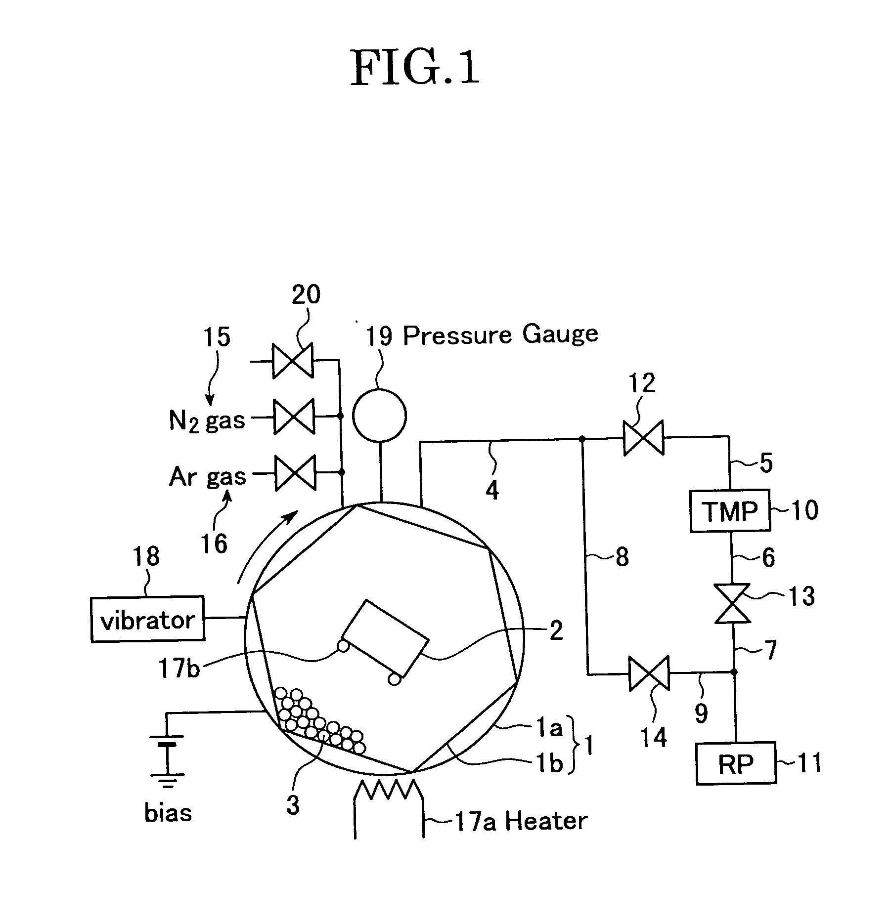
[0026]FIG. 1 is a diagram schematically showing a structure of a polygonal barrel sputtering device used in one embodiment according to the present invention. The polygonal barrel sputtering device is one for coating surfaces of fine particles (powder) with at least one of the metal catalyst, the oxide catalyst and the compound catalyst as ultra-fine particles having a grain diameter smaller than that of the fine particles (herein, the term “ultra-fine particle” means a fine particle having a grain diameter smaller than that of the fine particle) or thin film in a state free from impurities or with an extremely few impurities.

[0027] The polygonal barrel sputtering device has a vacuum container 1 for coating fine particles 3 with ultra-fine particles or thin films. The vacuum container 1 includes a cylindrical body 1a having a diameter of 200 mm and a barrel...


PUM

PropertyMeasurementUnit
diameteraaaaaaaaaa
pressureaaaaaaaaaa
pressureaaaaaaaaaa

Abstract

A fine particle uniformly holding a substance having a catalytic influence on a surface. Sputtering is performed by agitating or rotating the fine particles 3 in a vacuum container 1, which has a polygon inner cross-section shape, by rotating the vacuum container 1, having a rotating axis almost vertical to the cross-section, and the surfaces of the fine particles 3 are coated with super-fine particles having a smaller particle diameter than that of the fine particle, or a thin film. The super-fine particle or the thin film is composed of at least a metal catalyst or an oxide catalyst or a composite catalyst.

Description

TECHNICAL FIELD [0001] The present invention relates to a fine particle (for example, a fine particle having catalysis). Particularly, the present invention relates to a fine particle, a surface of which is coated with a thin film or the like in such a manner that, compared to conventional methods, impurities hardly come to be mixed in. Also, the present invention relates to a new preparation method of catalyst employing a barrel sputtering method, and a new catalyst. BACKGROUND ART [0002] A catalyst is prepared by allowing a carrier such as Al2O3 to support a substance having catalysis such as an active metal. As preparation methods of the catalyst, a coprecipitation method, a kneading method, an impregnation method or the like are available (refer to, for example, a non-patent document “Industrial catalysts: Catalysts leading to technical innovations”, Yoichi Nishimura, Takesige Takahashi; Baifukan, Sep. 9, 2002, pp. 72). The coprecipitation method is a method for preparing the ca...

Claims


Application Information

Patent Timeline
Patent Type & Authority Applications(United States)
IPC IPC(8): B32B5/16B01J37/02B01J23/42B01J37/34C23C14/00C23C14/14C23C14/22C23C14/34H01M4/04H01M4/86H01M4/88H01M4/90
CPCB01J23/42B01J37/0223B01J37/0238B01J37/347C23C14/0021C23C14/223Y02E60/50H01M4/48H01M4/50H01M4/52H01M4/8605H01M4/8871H01M4/9016H01M4/04Y02E60/10
Inventor ABE, TAKAYUKIHONDA, YUUJI
Owner TAKAYUKI ABE
Why Eureka
Try Eureka