Motor drive device and motor drive method

a three-phase brushless, motor drive technology, applied in the direction of motor/generator/converter stopper, electronic commutator, dynamo-electric converter control, etc., can solve the problems of insufficient phase characteristics control, pulse current rise, and difficult to accurately read peak pulse current flow, etc., to achieve the effect of reducing the number of motors, and improving the reliability of terminal difference voltag

Active Publication Date: 2007-09-20
COLLABO INNOVATIONS INC
View PDF25 Cites 38 Cited by
  • Summary
  • Abstract
  • Description
  • Claims
  • Application Information

AI Technical Summary

Benefits of technology

[0026]The motor drive device and motor drive method of the present invention apply a search pulse in a specific range to compare the terminal difference voltage with a specific value to determine the rotor position. The likelihood of immediately knowing the rotor position from the selected phase is therefore constant. The rotor can therefore be started by immediately energizing the appropriate drive phase after detecting the rotor position. The invention thus enables applying a torque signal to start the motor without determining the rotor position after selectively energizing specific phases. The search and start mode is thus shortened and the motor can be started more quickly. The reliability of the terminal difference voltage is also improved and the rotor position can be accurately detected because the terminal difference voltage is detected from the search pulse in a specific range.
[0027]The terminal difference voltage denoting the difference between the pseudo-neutral-point voltage and the motor terminal voltage of each phase has a hig...

Problems solved by technology

Sensorless drive technology that does not require a rotor position sensor has also been developed due to concerns about reliability, cost, and the environment.
A problem with EP Patent Application Publication No. 0251785 is that it is difficult to accurately read the peak pulse current flow when the rotor position search pulse is applied.
The technology taught in EP Patent Application Publication No. 0251785 therefore is difficult to use in inexpensive motors having insufficient phase characteristics control.
Furthermore, the pulse current rises in motors in which the coil inductance is reduced for high speed performance, and the current required to achieve a desired pulse current peak difference is extreme.
A problem with U.S. Patent Application Publication No. 2004/0056628 is that there is a range where the rotor position cannot be detected.
If the ...

Method used


Image

  • Motor drive device and motor drive method
  • Motor drive device and motor drive method
  • Motor drive device and motor drive method

Examples


embodiment 1

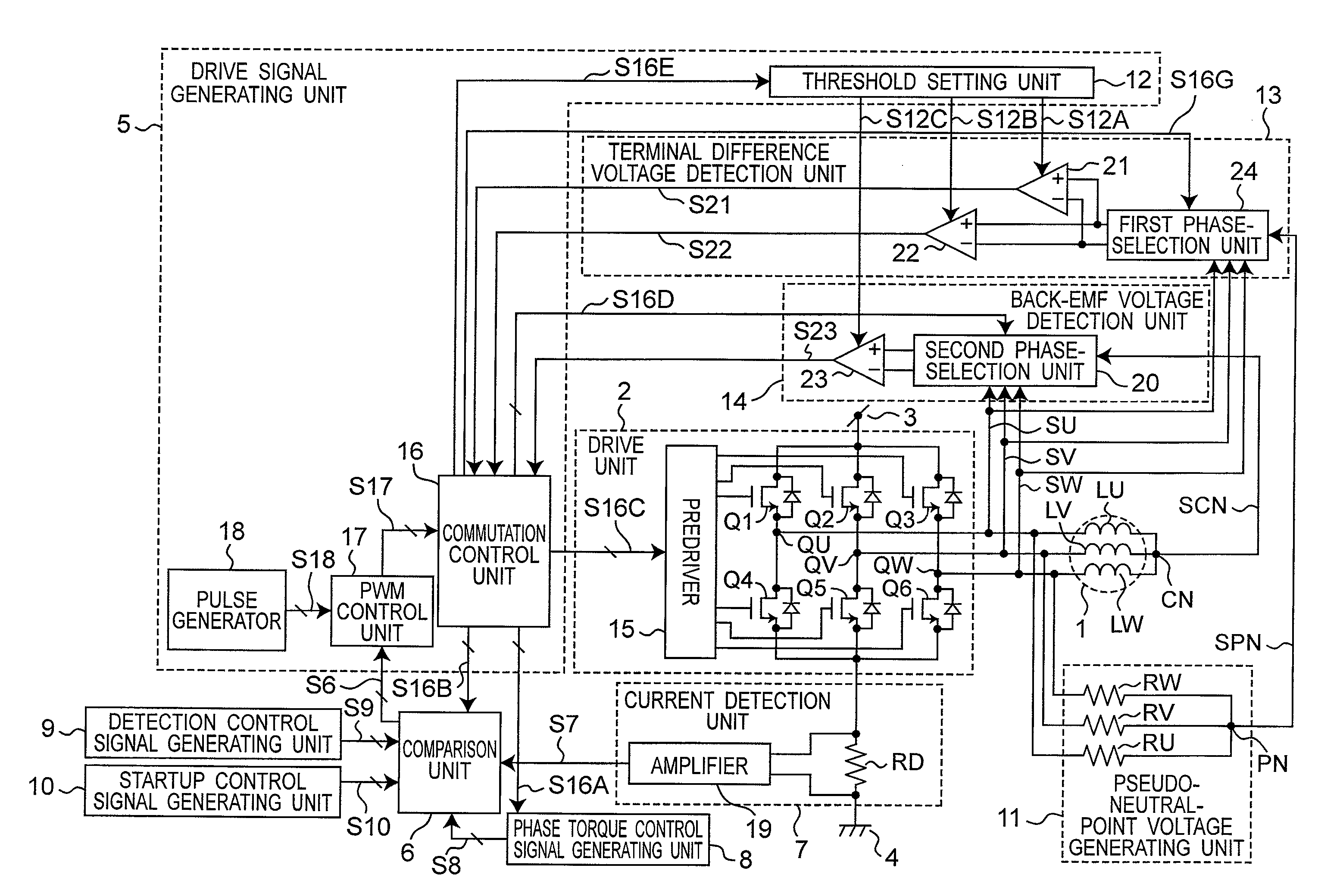
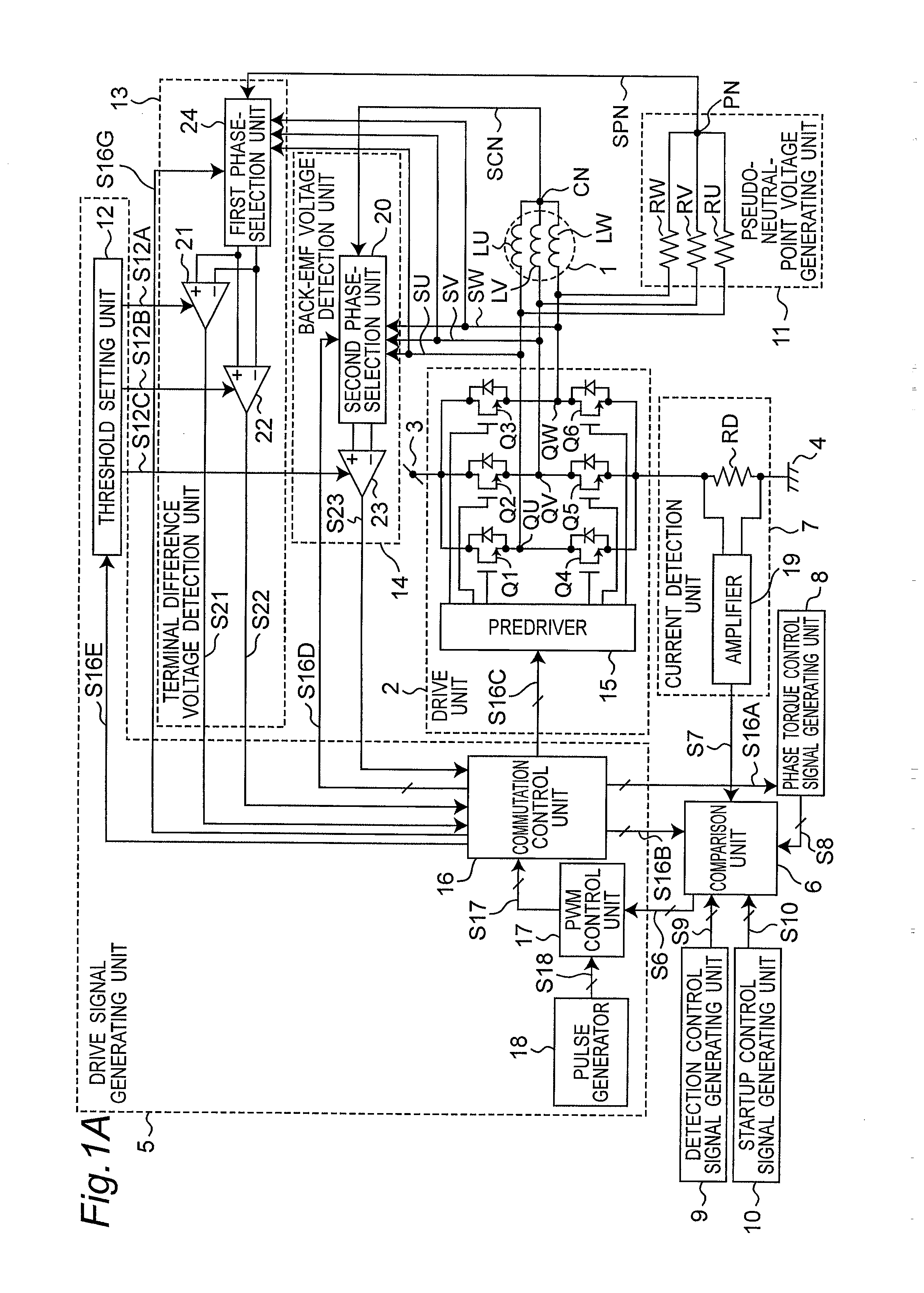
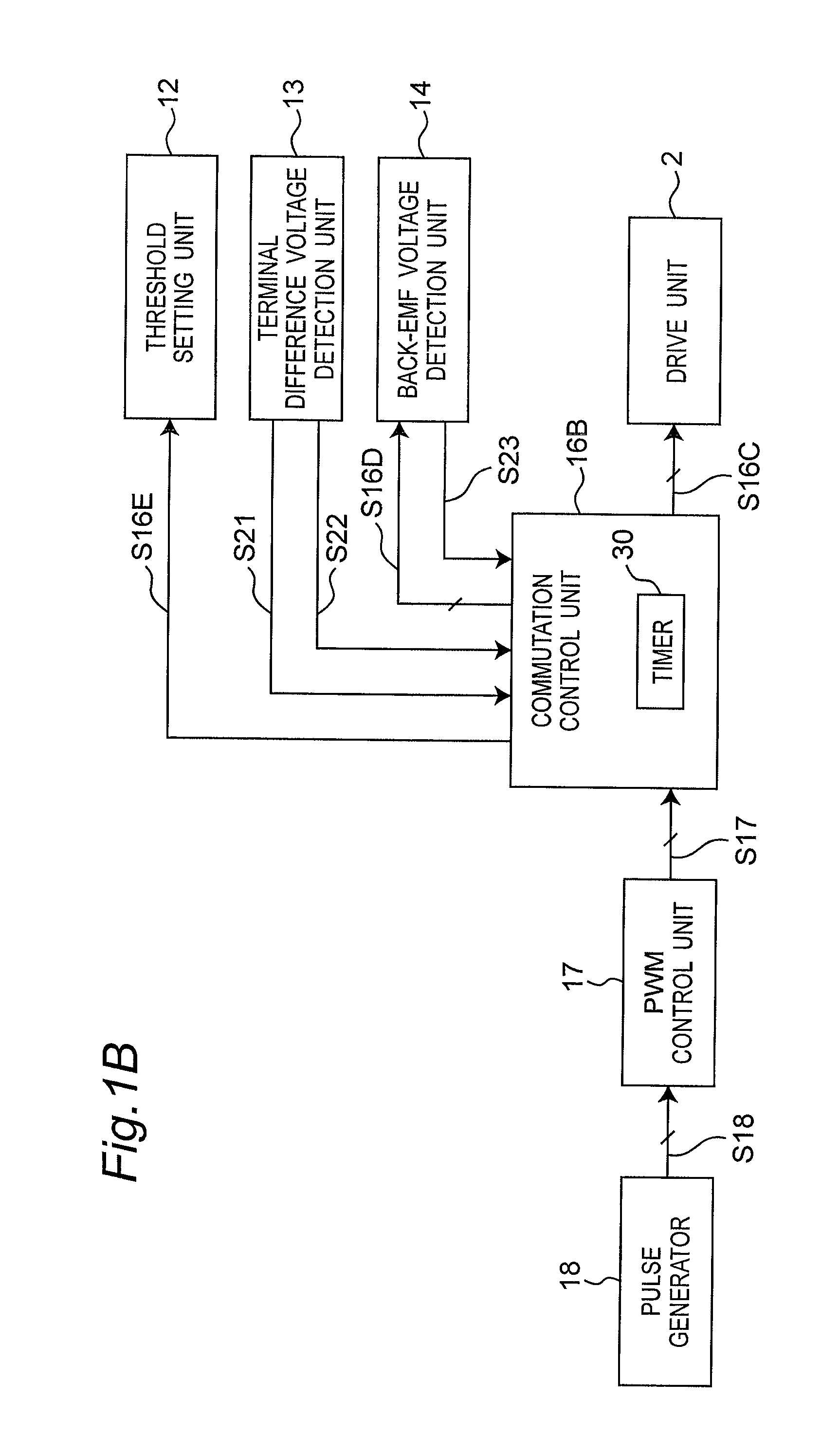
[0068]FIG. 1A is a circuit block diagram of a motor drive device according to a first embodiment of the invention. The motor drive device shown in FIG. 1A has a motor 1, a drive unit 2, a drive signal generating unit 5, a comparison unit 6, a current detection unit 7, a phase torque control signal generating unit 8, a detection control signal generating unit 9, a startup control signal generating unit 10, a pseudo-neutral-point voltage generating unit 11, a terminal difference voltage detection unit 13, and a back-EMF voltage detection unit 14.

[0069]The motor 1 has a three-phase fixed stator and a rotor that rotates around the stator. A three-phase motor 1 is used as the motor in this first embodiment of the invention, but the invention can be applied to any N-phase motor where N is an integer of two or more. The U-phase motor winding LU, V-phase motor winding LV, and W-phase motor winding LW are connected in common at neutral point CN, and the other end of each winding is respectiv...

third embodiment

[0463]This third embodiment is described with reference to the differences from the first embodiment. Other aspects of the arrangement, operation, and effect are the same as in the first embodiment above.

[0464]FIG. 33 is a block diagram showing the circuit arrangement of this third embodiment of the invention. This embodiment differs from the second embodiment in that input of the neutral point voltage SCN to the third phase selection unit 41 in the motor voltage detection unit 40 shown in FIG. 31 is eliminated to the fourth phase selection unit 41A shown in FIG. 33.

[0465]The commutation control unit 16A generates a phase selection signal S16H denoting the non-energized phase when two phases are energized, and outputs the phase selection signal S16H to the fourth phase selection unit 41A. The U-phase motor terminal voltage SU, V-phase motor terminal voltage SV, W-phase motor terminal voltage SW, and pseudo-neutral-point voltage SPN are also input to the fourth phase selection unit 4...

fourth embodiment

[0478]This fourth embodiment is described with reference to the differences from the first embodiment. Other aspects of the arrangement, operation, and effect are the same as in the first embodiment above.

[0479]Sensorless drive technology that does not require a rotor position sensor is used in many different fields due to concerns about reliability, increased cost, and environmental friendliness. The present invention can be used in fields where sensorless drive technology is used, including disk drive devices, for example. Disk drives include hard disk drive devices and optical disk drive devices. This fourth embodiment of the invention describes an arrangement using the present invention in an optical disk drive device as shown in FIG. 35.

[0480]Referring to FIG. 35, an optical pickup 130 emits a laser beam to an optical disc 100, and outputs an electrical signal representing information on the disc based on light reflected from the disc to the playback signal processing circuit 1...


PUM


Abstract

Problems with accuracy reading position detection signal peaks and minute phase differences in the detection current make motor drive control easily susceptible to differences in motor characteristics. The rotor position is determined based on whether or not a terminal difference voltage, which is the difference voltage between the motor terminal voltage and the pseudo-neutral-point voltage when the motor phases are selectively energized, exceeds a specific threshold value. The phase energized to start the motor is determined based on this determination and the motor is energized accordingly to start. Instead of switching directly from the search step at the initial rotor position to the back-EMF voltage mode, a search and start mode that creates initial rotor speed sufficient to start the motor is executed before entering the back-EMF voltage mode.

Description

BACKGROUND OF THE INVENTION[0001]1. Field of Invention[0002]The present invention relates to a three-phase brushless motor drive device and motor drive method enabling consistently starting quickly without requiring a rotor position sensor.[0003]2. Description of Related Art[0004]Brushless motors use a suitable number of windings in the stator winding to which current is supplied to apply a consistent amount of torque to the rotor. This requires knowing the electrical phase position of the rotor relative to the stator. Various kinds of rotor position sensors are used for knowing this relative phase position. Sensorless drive technology that does not require a rotor position sensor has also been developed due to concerns about reliability, cost, and the environment. Sensorless drive technologies generally detect the rotor position by reading the back electromotive force (back-EMF) voltage produced in the stator winding when the rotor is turning. However, because this back-EMF voltage...

Claims


Application Information

Patent Timeline
IPC IPC(8): H02P7/06H02P6/18H02P6/06H02P6/08H02P6/182H02P6/28
CPCH02P6/205H02P6/182H02P6/21
Inventor FUKAMIZU, SHINGOYAMAMOTO, YASUNORIMORI, HIDEAKIKUROSHIMA, SHINICHI
Owner COLLABO INNOVATIONS INC
Why Eureka
Try Eureka